Battery case laser welding clamp

A technology for laser welding and battery shells, applied in laser welding equipment, manufacturing tools, welding equipment, etc., can solve the problems of complex structure, inconvenient operation, and bad reputation of enterprises

Inactive Publication Date: 2015-07-01
邬汝源
View PDF6 Cites 7 Cited by
  • Summary
  • Abstract
  • Description
  • Claims
  • Application Information

AI Technical Summary

Problems solved by technology

However, the battery case laser welding jig in the prior art usually adopts a fixed positioning groove, and the positioning groove needs to be replaced when the battery is transformed, the structure is complicated, the operation is inconvenient, and the consistency between the center of the battery and the center of the index plate is poor
This not only reduces the production accuracy, affects the product quality, but also increases the production cost, which has a great adverse effect on the reputation of the enterprise.

Method used


Image

  • Battery case laser welding clamp
  • Battery case laser welding clamp

Examples


Embodiment Construction

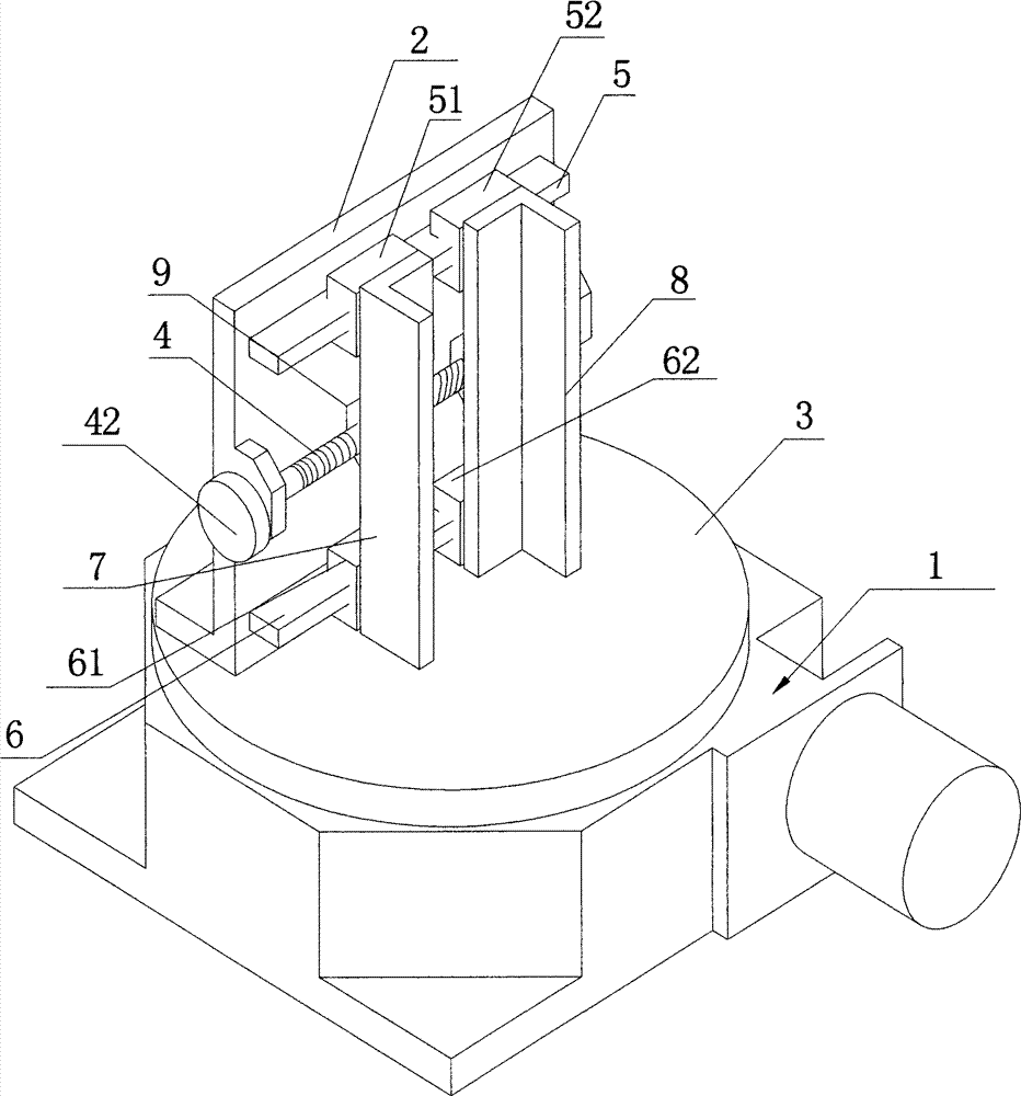
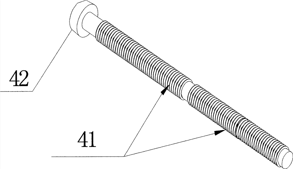
[0013] Such as figure 1 and figure 2 As shown, the battery case laser welding jig of the present invention includes a base 1 and a centering adjustment gap mechanism installed on the base 1. The centering adjustment gap mechanism includes a back plate 2 installed on the base 1. The base 1 and the An indexer 3 is installed between the backboards 2, an adjusting screw 4 is arranged on the horizontal central axis of the backboard 2, and the adjusting screw 4 is symmetrically provided with two guide rails up and down, and the first slide block 51 and the upper guide rail 5 are installed on the upper guide rail 5. The second slider 52, the third slider 61 and the fourth slider 62 are installed on the lower guide rail 6, the left battery splint 7 is fixed on the first slider 51 and the third slider 61, the second slider 52 and the second slider 61 Four sliders 62 are fixed with right battery clamping plate 8, left battery clamping plate 7 and right battery clamping plate 8 are pro...


PUM


Abstract

The invention aims to provide a battery case laser welding clamp. A centering gap adjusting mechanism can guarantee a stable structure, and the consistency of the center of a fixed battery and the center of an indexer disk is good when the type of the battery is replaced, so the product quality is improved. In order to achieve the effect, the battery case laser welding clamp comprises a pedestal and the centering gap adjusting mechanism which is arranged on the pedestal, wherein the centering gap adjusting mechanism comprises a back plate which is arranged on the pedestal; an indexer is arranged between the pedestal and the back plate; an adjusting screw is arranged on the horizontal middle axis of the back plate and penetrates through the nut to be connected with left and right battery clamping plates. Since the technical scheme is adopted, when the type of the battery of the battery case laser welding clamp is replaced, only a spinner is required to be rotated to drive the adjusting screw; the left battery clamping plate and the right battery clamping plate move symmetrically along the longitudinal middle axis of the back plate to guarantee that the consistency of the center of the battery between the left battery clamping plate and the right battery clamping plate and the center of the indexing disk and avoid reduction in machining precision due to replacement of the battery.

Description

technical field [0001] The invention relates to a fixture, in particular to a battery case laser welding fixture. Background technique [0002] Laser welding has always been a key process in the manufacturing process of lithium batteries. From stainless steel shells to aluminum shells to polymers, laser welding is widely used. With the continuous development of the industry, higher requirements have been put forward for the efficiency and quality of laser welding, and optical fiber transmission laser welding has been used. Since the main unit of the welding machine and the focusing head are connected flexibly, this method is easier to match with the assembly line , to achieve full automation. The appearance and performance of welds have also been significantly improved. However, there are further requirements for the battery case laser welding jig, and the precision requirements are higher. In the prior art, fixed positioning grooves are usually used on the battery shell ...

Claims


Application Information

Patent Timeline
IPC IPC(8): B23K26/70B23K37/04
CPCB23K37/0443B23K2101/36
Inventor 邬汝源
Owner 邬汝源
Why Eureka
Try Eureka