Integrated manufacturing method of composite material cavity member

A technology of composite materials and manufacturing methods, which is applied to the integrated manufacture of resin-based composite cavity components and the field of composite cavity component manufacturing, which can solve the problems of structural damage, difficulty in manufacturing, difficulty in mold assembly, disassembly and demolding and other issues to achieve the effect of simplifying the manufacturing process and reducing production costs

Inactive Publication Date: 2015-07-01
XIAN AIRCRAFT BRANCH OF XIAN AIRCRAFT INT
View PDF1 Cites 14 Cited by
  • Summary
  • Abstract
  • Description
  • Claims
  • Application Information

AI Technical Summary

Problems solved by technology

This type of cavity composite material parts is mainly manufactured by two methods: detachable mandrel method and splicing after parts are manufactured in pieces, but the manufacturing difficulty is relatively large. The main performance is that it is difficult or even impossible to demould after paving and curing.
Forced demoulding usually causes large residual stress in the structural parts, and even causes some structural parts to be destroyed
The manufacture of small-sized composite cavity components can meet the technical quality requirements by using the detachable core mold method, but the manufacture of large-scale composite cavity components cannot meet the requirements. Due to the large size and heavy weight of the mold, there are mold combinations , It is difficult to disassemble and demould, and the airtightness of the combined tooling is not easy to guarantee; while the composite cavity parts manufactured by the method of splicing after the parts are manufactured in pieces, there are parts butt joints, and the appearance is not smooth. Problems such as low dimensional accuracy

Method used


Image

  • Integrated manufacturing method of composite material cavity member
  • Integrated manufacturing method of composite material cavity member
  • Integrated manufacturing method of composite material cavity member

Examples


Embodiment Construction

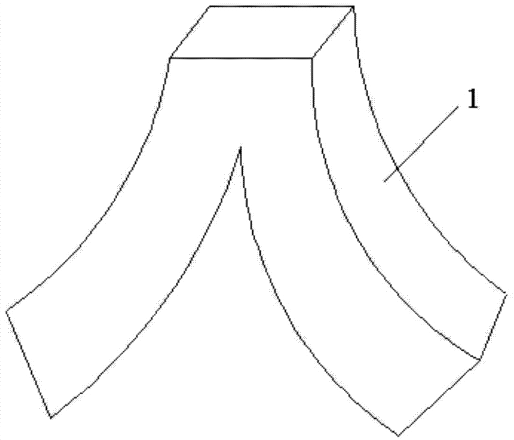
[0020] Referring to the accompanying drawings, the embodiment is based on figure 1 The parts shown are taken as an example. Part 1 is a "Y"-shaped composite conduit, which requires high manufacturing precision and must adopt an overall manufacturing process. The design theoretical model of the part is known.

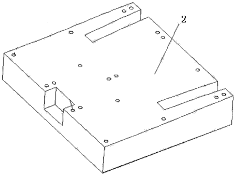
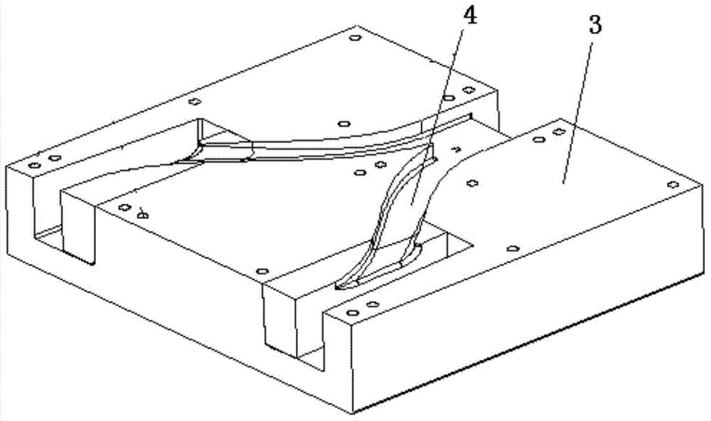
[0021] Base mold preparation, design and manufacture base molds according to the theoretical model (digital model) designed for composite material parts. The benchmark mold is the mold used to manufacture the water-soluble resin mandrel, mainly containing the mold cavity 4 formed by the upper mold 2, the lower mold 3 and the upper mold and the lower mold and the blocking plates (not shown) at both ends. The cavity formed by the mold must match the cavity of the composite part to be manufactured. The reference mold is made of non-metallic fiberglass, aluminum or steel, and the upper and lower templates are combined, fixed and molded by bolts.

[0022] When preparing the...


PUM


Abstract

The invention discloses an integrated manufacturing method of a composite material cavity part. The integrated manufacturing method comprises the following steps: manufacturing a standard mould according to a theoretical model of the part, wherein a cavity of the standard mould is coincident to that of the part; coating the surface in the cavity with one layer of water-soluble surface filling material and then injecting a water-soluble core material, compacting, closing, curing an upper mould and a lower mould, removing the standard mould after curing to form a water-soluble core mould of the part; spreading a composite material prepreg on the surface of the water-soluble core mould and curing; and finally, washing the water-soluble core mould by using water to form the composite material cavity part.

Description

technical field [0001] The invention relates to the technical field of aviation manufacturing, in particular to a method for manufacturing a cavity component of composite material, in particular to a special process method for integrally manufacturing a cavity component of resin-based composite material. Background technique [0002] Composite materials have the advantages of good designability, low density, high strength and modulus, good fatigue resistance, corrosion resistance and good processability, and have the characteristics of simultaneous formation of "materials and components". Therefore, composite materials have gradually become the main structural materials of advanced aircraft, and the amount is increasing. component application. With the continuous development and maturity of composite material design and manufacturing technology, the use of advanced composite materials in military and civil aircraft is also expanding, and advanced composite materials are gra...

Claims


Application Information

Patent Timeline
Patent Type & Authority Applications(China)
IPC IPC(8): B29C70/54B29C70/34B29C33/52C08K3/34C08K3/36
Inventor 焦竹叶武振林林星景新荣郭俊刚王瑾
Owner XIAN AIRCRAFT BRANCH OF XIAN AIRCRAFT INT
Why Eureka
Try Eureka