Binocular pupil light reflex tracking system

A tracking system and light reflection technology, applied in medical science, eye testing equipment, diagnosis, etc., can solve problems such as inconvenient operation, low frame rate of camera acquisition, and limited measurement accuracy, so as to improve frame rate and tracking Accuracy, ensuring the accuracy of measurement results, and meeting storage requirements

Active Publication Date: 2015-07-01
SUZHOU INST OF BIOMEDICAL ENG & TECH CHINESE ACADEMY OF SCI
View PDF5 Cites 9 Cited by
  • Summary
  • Abstract
  • Description
  • Claims
  • Application Information

AI Technical Summary

Problems solved by technology

[0007] (1) Measurement content and accuracy are limited: hand-held pupil penlights, flashlights, etc. cannot objectively, quantitatively and accurately measure the pupil size and light reflection, including the inability to measure the light reflection latency and pupil contraction speed, etc. ;
[0008] (2) Poor portability: the pupil detector is bulky and heavy, and needs to be placed in a flat environment, so it is not suitable for use in the field;
[0009] (3) The detection object is limited: the existing equipment, the stimulation time of the stimulating light source is fixed, and the disease cannot be checked for special patients, such as patients with severe coma;
[0010] (4) Inconvenient operation and susceptible to interference from subjective factors: Traditional pupil detector equipment requires manual participation in many test procedures. The differences in manual operations and subjective judgments may lead to inaccurate tests and require the cooperation of the subjects Very high, it will bring discomfort to the subject;
[0011] (5) Poor real-time performance: The camera acquisition frame rate of the existing pupil detection equipment is low, and the real-time performance of the pupil measurement software is poor, so the measurement accuracy is limited;
[0012] (6) Limited operating efficiency: Existing portable devices do not support binocular pupillary light reflex inspection, and cannot screen patients with abnormal indirect light reflex;
[0013] (7) The measurement result is not intuitive: the existing pupil light reflex equipment provides the measurement result parameters, and there is no intuitive change curve

Method used


Image

  • Binocular pupil light reflex tracking system
  • Binocular pupil light reflex tracking system
  • Binocular pupil light reflex tracking system

Examples


Embodiment 1

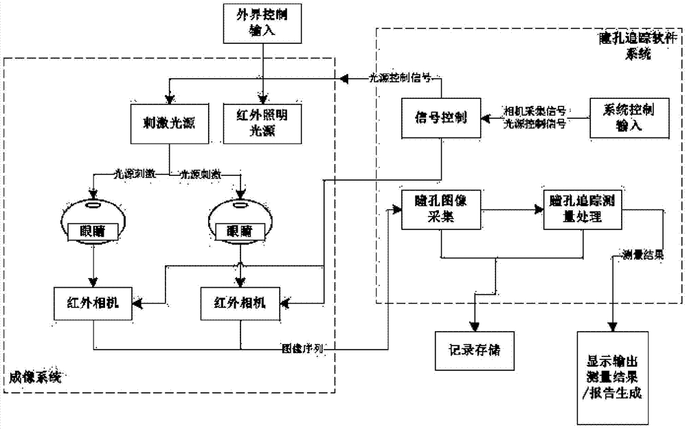
[0039] This embodiment illustrates the system architecture of the present invention.

[0040] combined with figure 1, which is a schematic diagram of the system structure of the present invention, and the system includes a graspable binocular pupil detection device imaging system and a pupil tracking measurement module. Among them, the imaging system includes two infrared cameras, two infrared lighting sources, two stimulating light sources, a grasping device and a single-chip microcomputer. The infrared camera, lighting source, stimulating light source and single-chip microcomputer are integrated inside the grasping device. Single-chip microcomputer connection, the single-chip microcomputer is responsible for signal control and data input and output; the pupil tracking measurement module is integrated in the single-chip microcomputer, and the image collected by the single-chip microcomputer is tracked and measured, and the measurement results are analyzed and processed, and f...

Embodiment 2

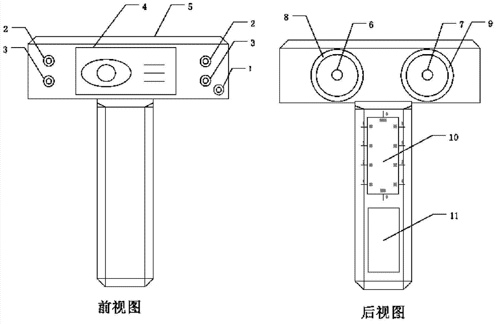
[0046] This embodiment is carried out on the basis of the foregoing embodiment 1. The difference from the foregoing embodiment 1 is that this embodiment describes the appearance and structure of the system of the present invention in detail.

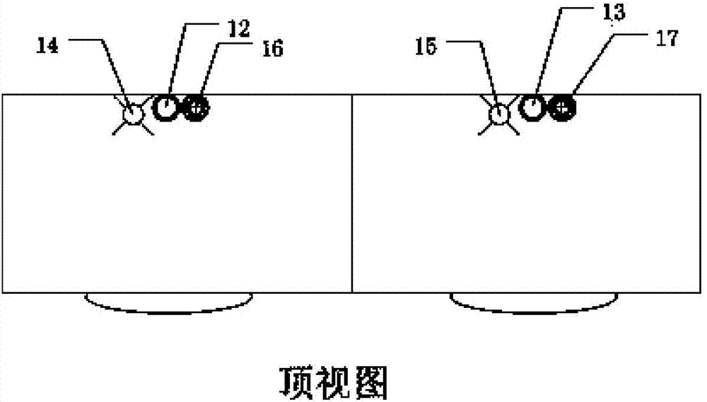
[0047] In conjunction with accompanying drawing 2, it is a schematic diagram of an appearance structure of the present invention, including a front view and a rear view ( Figure 2a ) and top view ( Figure 2b ).

[0048] The present invention is a grasping measuring device, which includes infrared cameras 12 and 13, and the two cameras are independently and directly controlled by a single-chip microcomputer to respectively complete image acquisition and finally connect with the pupil tracking measurement module; combined with the attached Figure 2a , the top of the gripping device is the measuring part, and the lower part is the handle.

[0049] Infrared lighting sources 14 and 15 are installed in the device, which are controlled by ...

Embodiment 3

[0056] This embodiment is carried out on the basis of the foregoing embodiment 1 or 2. The difference from the foregoing embodiments is that this embodiment further improves the grasping device.

[0057] The binocular pupil light reflex tracking system includes a grasping device. The top of the grasping device is a measuring part, and the lower part is a handle. Both the measuring part and the handle have built-in spaces for installing infrared cameras, infrared lighting sources, and single-chip microcomputers. , stimulating light source, and power supply; the handle of the grasping device is equipped with a single-chip microcomputer and power supply; the front surface of the measuring part of the grasping device is embedded with a display screen, which is connected to the single-chip microcomputer; the bottom of the right side of the display screen has a On and off buttons. There are stimulus light source knobs and pupil tracking buttons on the left and right sides of the disp...


PUM


Abstract

The invention discloses a binocular pupil light reflex tracking system. The binocular pupil light reflex tracking system comprises a grabbing type binocular pupil detection device imaging system and a pupil tracking and measuring module. The imaging system comprises two infrared cameras, two infrared lighting light sources, two stimulation light sources, a grabbing type device and a single-chip microcomputer. The infrared cameras, the lighting light sources, the stimulation light sources and the single-chip microcomputer are integrated in the grabbing type device, the cameras and the light sources are connected with the single-chip microcomputer, and the single-chip microcomputer is in charge of signal control and data input and output. The pupil tracking and measuring module is integrated in the single-chip microcomputer, images collected by the single-chip microcomputer are tracked and measured, and the measuring result is analyzed. The system further comprises a movable seat matched with a handle, and a suspension assembly. The system is high in adaptability, capable of being applied to first-aid and field occasions and the like, and wide in application prospect.

Description

technical field [0001] The invention belongs to the field of visual detection, and specifically relates to a binocular pupil light reflection tracking system, which includes an infrared camera, an infrared lighting source, a stimulating light source, a grasping device, a measurement display device, a single-chip microcomputer control, a data processing control module and a pupil The tracking measurement system module is suitable for medical applications in clinical ophthalmology, neurosurgery, psychiatry and related fields. Background technique [0002] When the human eye is stimulated by light, the pupil narrows, which is called the pupillary light reflex. The constriction of the pupil is accomplished by the pupillary sphincter muscle innervated by the parasympathetic nerve in the oculomotor nerve, and the dilation of the pupil is accomplished by the pupillary dilator muscle innervated by the sympathetic nerve. The reflex on the same side is called the direct light reflex,...

Claims


Application Information

Patent Timeline
Patent Type & Authority Applications(China)
IPC IPC(8): A61B3/10
Inventor 董月芳付威威陈奭
Owner SUZHOU INST OF BIOMEDICAL ENG & TECH CHINESE ACADEMY OF SCI
Why Eureka
Try Eureka