Disc diameter detector

A detector and disk diameter technology, applied in the field of building foundation engineering, can solve problems such as affecting measurement efficiency, high technical requirements, delaying concrete pouring, etc., to achieve the effect of improving detection efficiency, increasing measurement range, and ensuring normal implementation.

Active Publication Date: 2015-07-01
HONGYUANZHONGKE BEIJING FOUND ENG CO LTD
View PDF9 Cites 2 Cited by
  • Summary
  • Abstract
  • Description
  • Claims
  • Application Information

AI Technical Summary

Problems solved by technology

Like ordinary pile foundations, cast-in-situ piles with extruded and expanded branch plates are usually underground or underwater. The construction process is complicated, the technical requirements are high, the construction is difficult, and quality problems are prone to occur. Therefore, the quality inspection of cast-in-situ piles with extruded and expanded branch discs is particularly important.
However, the traditional aperture detector we use now cannot complete the detection under many disk diameter conditions; in addition, because the aperture disk diameter detection needs to be carried out immediately after the hole-forming support disk is completed, it is closely connected with the subsequent process, while the original detection When the equipment encounters contact with the hole wall or the unexpected vibration of the probe during the drilling process, it is very easy to open the equipment, resulting in the need to lift the equipment out of the hole and re-drill the hole
This seriously affects the measurement efficiency, delays the pouring of concrete, and affects the quality of the pile. Therefore, accurate and efficient measurement of the disc diameter is a problem that needs to be solved at present.

Method used


Image

  • Disc diameter detector
  • Disc diameter detector
  • Disc diameter detector

Examples


Embodiment Construction

[0028] In order to facilitate those skilled in the art to understand the technical solutions and beneficial effects of the present invention, specific implementation methods are described below in conjunction with the accompanying drawings.

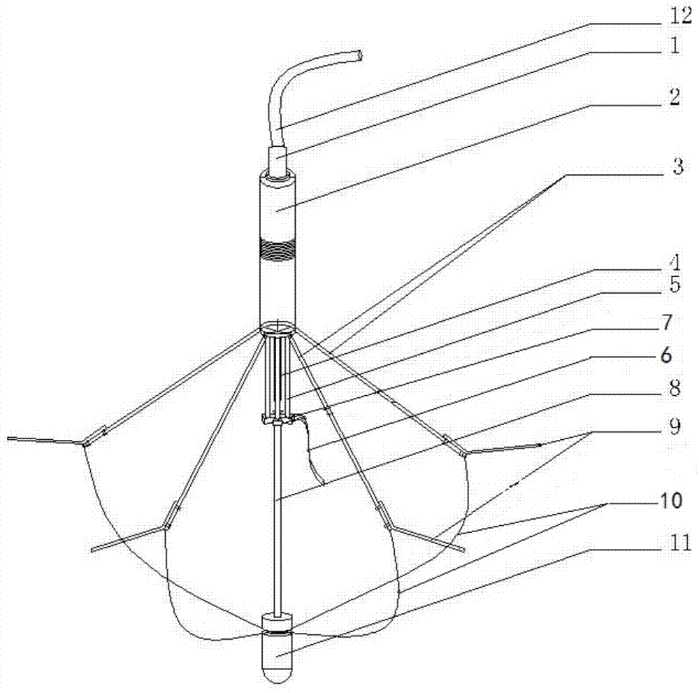
[0029] see figure 1 As shown, it is a schematic structural view of the disk diameter detector of the present invention, including a downhole cable 12, which is connected to the upper part of the sleeve 2, and the connection is socketed with a rubber protective sleeve 1, which can be directly held by the downwell cable 12. The disc diameter detector is put into the pile hole, and the weight of the whole instrument is borne by the downhole cable 12. The rubber protective sleeve 1 can reduce the external impact force, and prevent the joint of the downhole cable 12 and the sleeve 2 from colliding with the wellhead frame due to excessive swing when the disc diameter detector puts out the wellhead, so as to protect the downhole cable 12 from be...


PUM


Abstract

The invention provides a disc diameter detector which comprises a sleeve, a well descending cable, measuring legs, a supporting pillar, a connection rod, pull wires, a pressure compensator and a binding belt. The sleeve is internally provided with a sealing cylinder in a sealed mode. The sealing cylinder is internally provided with a sliding potentiometer. The well descending cable is connected with the upper portion of the sleeve in a sealed mode. The upper ends of the measuring legs are connected with the lowermost end of the cylinder wall of the sleeve, and the lower ends of the measuring legs are fixedly connected with legs on the outer sides. The upper end of the supporting pillar is connected with the lower portion of the sleeve, and the lower end of the supporting pillar is connected with a plum-blossom-shaped disc. The upper end of the connection rod is fixedly connected with the plum-blossom-shaped disc, and the lower end of the connection rod is connected with a control motor. One end of each pull wire is fixedly connected with the lower end of the corresponding measuring leg, and the other end of each pull wire is wound on the control motor. The pressure compensator is an oil-resisting rubber pipe and communicated with the sealing cylinder. The binding belt is fixed to one side face of the plum-blossom-shaped disc. By means of the disc diameter detector, disc diameters of different sizes can be measured, meanwhile detection efficiency is improved, and the success rate of hole descending detection is increased.

Description

technical field [0001] The invention belongs to the field of building foundation engineering, and in particular relates to a disc diameter detector for detecting the hole diameter and disc diameter of cast-in-situ piles with extruded and expanded support discs. Background technique [0002] At present, cast-in-situ piles with extruded and expanded branches are developing rapidly in the field of pile foundations. With the wide application of cast-in-situ piles with extruded and expanded branches in the pile foundation treatment of various construction projects, cast-in-situ piles with extruded and expanded branches have become a kind of engineering construction. Important form of pile foundation. The hole-forming and plate-forming quality of the cast-in-situ piles with extruded and expanded branch plates is directly related to the safety of the entire project construction. Like ordinary pile foundations, cast-in-situ piles with extruded and expanded branch plates are usually...

Claims


Application Information

Patent Timeline
Patent Type & Authority Applications(China)
IPC IPC(8): E02D33/00E21B47/08
Inventor 王春龙王春虎
Owner HONGYUANZHONGKE BEIJING FOUND ENG CO LTD
Why Eureka
Try Eureka