
Method of manufacturing differential device

A differential device and manufacturing method technology, applied in the direction of differential transmission, transmission, transmission parts, etc., can solve the problems of reduction of production cost, ring gear welding deformation, more welding processes, etc., to improve efficiency, Good welding, reduce thermal deformation effect

Inactive Publication Date: 2015-07-01
MUSA PRECISION IND CO LTD
View PDF6 Cites 4 Cited by
  • Summary
  • Abstract
  • Description
  • Claims
  • Application Information

AI Technical Summary

Problems solved by technology

This structure is effective in reducing the welding deformation of the ring gear, but it is difficult to reduce the production cost due to the increase in the number of welding processes.
In addition, when the work window is formed to be large in order to facilitate the processing of the inner surface of the differential case or to facilitate the insertion of the differential mechanism into the differential case, the work window may be A concave portion is formed deep into the side surface of the flange on the side of the first bearing boss. Such a concave portion hinders the welding of the ring gear on both sides of the flange and causes welding deformation of the ring gear.

Method used


Image

  • Method of manufacturing differential device
  • Method of manufacturing differential device
  • Method of manufacturing differential device

Examples


Embodiment Construction

[0031] Embodiments of the present invention will be described below with reference to the drawings.

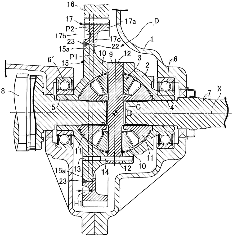
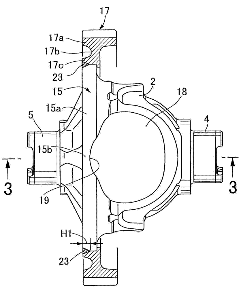
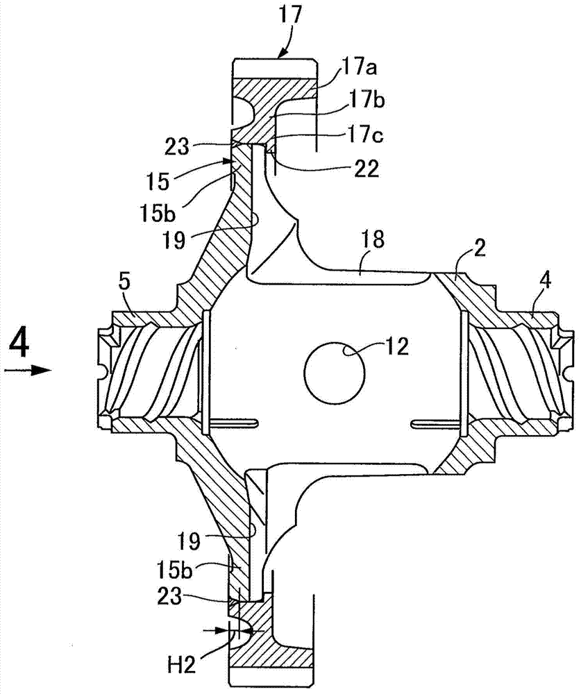
[0032] exist figure 1 Among them, the differential device D is accommodated in the transmission case 1 of the vehicle. This differential device D is composed of a differential case 2 and a differential mechanism 3 housed in the differential case 2 . A first bearing boss 4 and a second bearing boss 5 aligned on the same axis X are integrally formed on the right side and the left side of the differential case 2, and these first and second bearing bosses 4 , 5 are supported on the transmission housing 1 via bearings 6, 6', and support the right axle 7 and the left axle 8.

[0033] The differential mechanism 3 is composed of: a pinion shaft 9 held on the differential case 2 in a manner perpendicular to the axis X; a pair of pinion gears 10 supported by the pinion shaft 9; And a pair of side gears 11 are spline-coupled to the inner ends of the axles 7 and 8 and meshed with the p...


PUM


Abstract

In a method of manufacturing a differential device, a hub of a ring gear is press-fitted to a flange from a first bearing boss side, then a press-fit portion between the flange and the ring gear is equally divided into a plurality of divided regions arranged along a peripheral direction, and simultaneously the divided regions are welded. Accordingly, the press-fit portion between the flange and the ring gear can be efficiently welded while welding distortion of the ring gear is eliminated or reduced even in a case where work windows of a differential case cut into a side surface of the flange on the first bearing boss side to form recessed portions.

Description

technical field [0001] The present invention relates to a differential device, and more particularly to a method of manufacturing the differential device. The first and second bearing bosses are aligned on the same axis, and an annular flange is integrally formed at the middle portion of the differential case offset from the center to the second bearing boss side, and On the peripheral wall of the differential case opposite on a diametrical line perpendicular to the axis, an operation window for inserting the differential mechanism is provided, and the ring gear is pressed into the outer periphery of the flange. surface, and then weld the press-fit parts of these flanges and the ring gear on the side of the second bearing boss. Background technique [0002] Such a differential device is known as disclosed in Patent Document 1 below. [0003] Patent Document 1: WO2013-18223 Publication [0004] In the content disclosed in the above-mentioned Patent Document 1, the thicknes...

Claims


Application Information

Patent Timeline
Patent Type & Authority Applications(China)
IPC IPC(8): F16H57/023F16H48/40F16H48/08B23P19/02
CPCF16H48/38F16H2048/382F16H48/40F16H2048/385Y10T29/49464
Inventor 柳濑阳一
Owner MUSA PRECISION IND CO LTD
Learn More