Automatic cleaning oil tank

An automatic cleaning and oil tank technology, which is applied in the direction of engine components, lubricating oil containers, engine lubrication, etc., can solve the problems of shortening the service life of lubricating oil, increasing maintenance costs, and deteriorating equipment operation status, so as to avoid accidents, The effect of reducing maintenance costs and avoiding overpressure at the outlet

Inactive Publication Date: 2015-07-01
TIANJIN QIXING PRECISION MACHINERY
View PDF0 Cites 2 Cited by
  • Summary
  • Abstract
  • Description
  • Claims
  • Application Information

AI Technical Summary

Problems solved by technology

[0004] Since the lubricating oil for circulating lubrication needs to be used for a long time, the internal impurities will accumulate more and more. Although it passes through a three-stage filtration system such as filters and screens, it is easy to cause the lubricating oil to deteriorate or the impurities to enter the friction pair again, resulting in The equipment running state becomes worse, and the service life of lubricating oil becomes shorter
At this time, only the lubricating oil has to be replaced, which causes great waste; at the same time, due to the large amount of impurities, it will cause blockage of the three-stage filter system such as filters and filter screens, overpressure at the outlet of the circulating pump, and insufficient oil supply for power equipment, resulting in equipment breakdown. Accidents, increased repair costs

Method used


Image

  • Automatic cleaning oil tank

Examples


Embodiment Construction

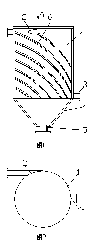
[0018] figure 1 It is a structural schematic diagram of the present invention, figure 2 for figure 1 View along direction A, as shown in the figure: the self-cleaning circulating oil tank of this embodiment includes a cylindrical box 1, and the cylindrical box 1 is provided with an oil inlet 1 near the upper end and an oil outlet near the lower end. Port 3, the oil inlet direction of the oil inlet is along the tangential direction of the inner wall of the cylindrical box, and the lower end surface of the cylindrical box 1 is an inverted tapered structure 4.

[0019] The inner wall of the cylindrical box is provided with a spiral blade plate 6, and the expansion direction of the spiral blade plate 6 from top to bottom is consistent with the only direction; the structure of the spiral blade 6 is added to further guide the lubricating oil to swirl, so that the impurities are quickly Deposits to increase the separation effect.

[0020] The bottom of the lower end surface of th...


PUM


Abstract

The invention discloses an automatic cleaning oil tank. The automatic cleaning oil tank comprises a cylindrical tank body, wherein an oil inlet near the upper end and an oil outlet near the lower end are formed in the cylindrical tank body; an oil inlet direction of the oil inlet is in the tangential direction of the inner wall of the cylindrical tank body; and the lower end surface of the cylindrical tank body is an inverted conical structure. The oil inlet of the oil tank is in the tangential direction and the bottom of the oil tank is the inverted conical structure, so that entering lubricant is in a cyclonal state. As the density of impurities is higher than the density of the lubricant, the impurities can enter the conical bottom and be accumulated in the cyclonal process, and the impurities of the lubricant in the upper space of the conical bottom of the oil tank are fewer. Accordingly, the purposes of automatically cleaning the impurities in the lubricant and guaranteeing the quality of the lubricant are achieved, and thus all frictional pairs of power equipment are normally operated; meanwhile, the blockage frequency of such three-level filter systems as filters and filter screens can be reduced; the problems of excess pressure in an outlet of a circulating pump and insufficient oil supply of the power equipment are prevented; the equipment accidents are prevented; and the maintenance cost is reduced.

Description

technical field [0001] The invention relates to an auxiliary equipment of a lubricating oil distribution station, in particular to a forced lubricating circulating oil tank. [0002] Background technique [0003] The lubricating oil station is an indispensable auxiliary equipment system for large-scale power machinery; the lubricating oil of large-scale power equipment generally adopts forced circulation lubrication. The lubricating oil station generally includes a fuel tank, a circulating pump and a filter; the circulating pump pumps the lubricating oil in the fuel tank to the lubricating part through the filter to achieve lubrication, and the lubricated lubricating oil returns to the fuel tank to form a cycle. It can lubricate the friction pair well, and take away heat and impurities at the same time, which is beneficial to the long-term operation of the friction pair. [0004] Since the lubricating oil for circulating lubrication needs to be used for a long time, the in...

Claims


Application Information

Patent Timeline
Patent Type & Authority Applications(China)
IPC IPC(8): F16N19/00F16N39/00
Inventor 李洪建
Owner TIANJIN QIXING PRECISION MACHINERY
Why Eureka
Try Eureka