Fluid conveying pipe leakage acoustic emission time-frequency positioning method

A pipeline leakage and positioning method technology, which is applied in the pipeline system, gas/liquid distribution and storage, mechanical equipment, etc., can solve the problems of large positioning error, weak signal correlation, and large time delay estimation error, etc., to solve the positioning error big effect

Active Publication Date: 2015-07-01
重庆富世恒睿物联网科技有限公司
View PDF13 Cites 38 Cited by
  • Summary
  • Abstract
  • Description
  • Claims
  • Application Information

AI Technical Summary

Problems solved by technology

This is mainly because the cross-correlation location method requires the acoustic emission signal of the leakage to transmit along the pipeline at a constant sound velocity, but in fact the acoustic emission signal of the pipeline leakage has the characteristics of wide frequency band, frequency dispersion and multi-mode, and different modes have different characteristics. The degree of dispersion and different transmission speeds, that is, the propagation speed of the leakage acoustic emission signal in the pipeline is closely related to the frequency and mode type, and the constant sound level is difficult to determine
If the correlation analysis is directly performed on the collected acoustic emission signals and the location of the leak is performed, the correlation of the signals is weak, and the delay estimation error is large; Will cause a large leakage positioning error
Therefore, the acoustic emission pipeline leak detection method based on cross-correlation has a large positioning error, and is not suitable for the situation where the dispersion is serious and the constant sound velocity is difficult to determine.

Method used


Image

  • Fluid conveying pipe leakage acoustic emission time-frequency positioning method
  • Fluid conveying pipe leakage acoustic emission time-frequency positioning method
  • Fluid conveying pipe leakage acoustic emission time-frequency positioning method

Examples


Embodiment

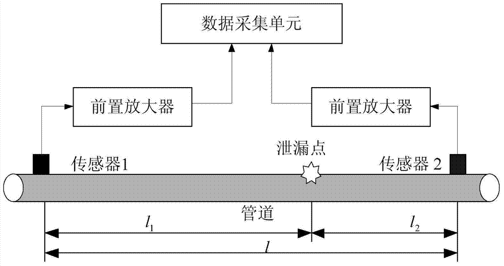
[0054] The pipeline leakage acoustic emission time-frequency positioning method proposed by the present invention is applied to the gas pipeline leakage detection experimental platform, wherein the total length of the pipeline is 110m, the air pressure is within 0.2MPa, and the geometric and material parameters of the pipeline are as shown in Table 1:

[0055] Table 1 Pipeline geometry and material parameters used in experiments

[0056]

[0057] In the table, a and b are the inner diameter and outer diameter of the pipe respectively; μ and ρ are the Poisson’s ratio and density of the pipe wall material respectively; G and E are the shear modulus and Young’s modulus of the pipe wall material respectively; c 0 is the rod speed corresponding to the tube wall material,

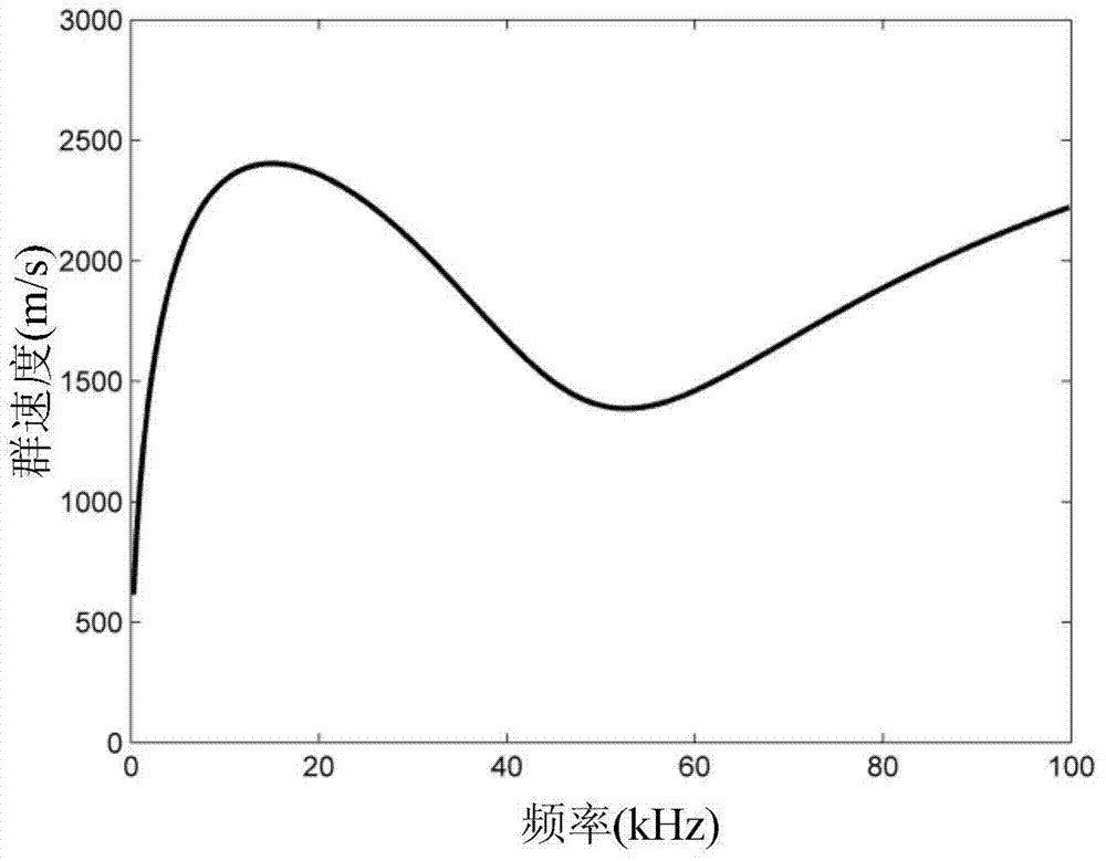
[0058] Using the geometric structure and material parameters of the pipeline, the numerical solution of the pipeline dispersion equation can be obtained, and the group velocity dispersion curve is as follows...


PUM


Abstract

The invention relates to a fluid conveying pipe leakage acoustic emission time-frequency positioning method. The fluid conveying pipe leakage acoustic emission time-frequency positioning method comprises the following steps of picking up acoustic emission signals through an acoustic sensor and a vibration sensor which are arranged at two ends of a pipe leakage point respectively and performing cross-correlation analysis on the acoustic emission signals which are picked up; performing time-frequency analysis on cross-correlation functions of the two channels of acoustic emission signals through smooth pseudo Wigner-Ville time-frequency distribution; extracting the time and frequency information corresponding to time-frequency spectrum peak values of the cross-correlation functions of the acoustic emission signals during pipe leakage; serving the time information corresponding to the peak values as the time delay of two observation signals and determining the transmission speed of the leakage acoustic emission signals along a pipe through table look-up on a frequency dispersion curve according to the frequency information of the peak values; determining the pipe leakage position through the time delay and the timely determined acoustic speed. The fluid conveying pipe leakage acoustic emission time-frequency positioning method can be used for performing accurate positioning on the leakage point under the conditions that the leakage acoustic emission frequency dispersion of the fluid conveying pipe is serious and the acoustic speed is difficult to be determined and meanwhile the correlation functions of the single frequency leakage signals are extracted for the time delay estimation and accordingly the degree of correlation of the leakage signals is enhanced and the leakage positioning error is further reduced.

Description

technical field [0001] The invention belongs to the technical field of pipeline leakage detection, and relates to a time-frequency positioning method for acoustic emission of fluid conveying pipeline leakage. Background technique [0002] As an efficient and convenient fluid transportation method, pipeline has been widely used in the transportation of oil, natural gas and other fluids. Due to natural or man-made reasons: pipeline aging, corrosion, geological subsidence, irregular construction, etc., pipeline leakage occurs from time to time. Pipeline leakage will cause resource waste, environmental pollution, and even explosion, poisoning and other vicious accidents, posing a serious threat to people's lives and property. Pipeline leakage detection and location technology is very necessary to reduce the harm caused by pipeline leakage. [0003] At present, the pipeline leakage detection methods used at home and abroad mainly include the flow balance method, the instantaneo...

Claims


Application Information

Patent Timeline
Patent Type & Authority Applications(China)
IPC IPC(8): F17D5/06
Inventor 李帅永王平
Owner 重庆富世恒睿物联网科技有限公司
Why Eureka
Try Eureka