Firing method of wall type opposed firing boiler

A technology of opposed combustion and combustion method, which is applied in the field of thermodynamic machinery, and can solve the problems of shortened combustion time of pulverized coal particles, high temperature slagging on the wall surface of the main combustion zone, and poor combustion stability.

Active Publication Date: 2015-07-01
YANTAI LONGYUAN POWER TECH
View PDF5 Cites 7 Cited by
  • Summary
  • Abstract
  • Description
  • Claims
  • Application Information

AI Technical Summary

Problems solved by technology

[0007] In addition, on the one hand, delayed ignition will shorten the combustion time of pulverized coal particles in the furnace, increase the carbon content of fly ash and large slag, and affect boiler efficiency.
At the same time, the lower temperature level will also affect the stability of the combustion flame in the furnace
On the other hand, when the high-temperature mixed flue gas that will not be completely combusted in the furnace in the future flows through the upper part of the furnace and the heating surface of the horizontal flue, it will continue to burn and release heat, often causing insufficient cooling water on these heating surfaces, increasing the high-temperature slagging on these heating surfaces, Even the risk of overheating the tube burst
[0008] Since the excess air coefficient of the entire main combustion zone A is less than 1, the near-wall area of ​​the main combustion zone A is also in a strong reducing atmosphere, and the strong reducing atmosphere reduces the ash melting point of coal. When the temperature is low, it will often cause high temperature slagging on the wall of the main combustion zone, which also affects the effective heat transfer of the boiler.
[0009] In short, the use of furnace air staged combustion technology to reduce NOx emissions in wall-type opposed combustion boilers will cause a series of problems such as delayed coal ignition, poor combustion stability, low burnout rate, and high-temperature slagging.

Method used


Image

  • Firing method of wall type opposed firing boiler
  • Firing method of wall type opposed firing boiler
  • Firing method of wall type opposed firing boiler

Examples


no. 1 example

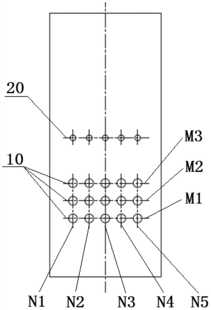
[0057] figure 2 It is a schematic diagram of the layout of the burner and the exhaust air nozzle on the boiler body of the wall-type opposed combustion boiler adopting the furnace air staged combustion technology corresponding to the first embodiment of the present invention.

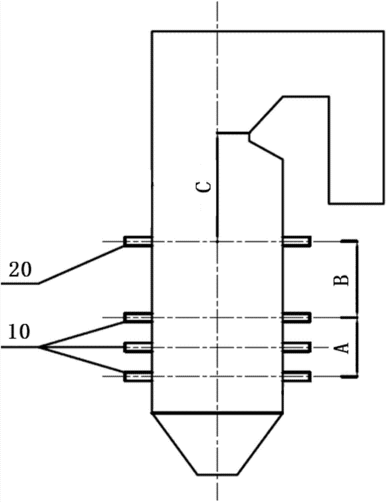
[0058] In the wall-type opposed combustion boiler corresponding to the combustion method of the first embodiment, the front wall and the rear wall of the boiler are arranged as figure 2 Shown are a plurality of burners 10 and a plurality of overburning air nozzles 20 disposed above the plurality of burners 10 . Wherein, the burner 10 is specifically a swirl pulverized coal burner.

[0059] like figure 2 As shown, in the first embodiment, 15 burners 10 arranged in a matrix are arranged on the front wall of the boiler body, and the 15 burners 10 are divided into three rows and five columns, that is, in the first embodiment, M =3, N=5.

[0060] figure 2 Among them, the 15 burners 10 are the first ...

no. 2 example

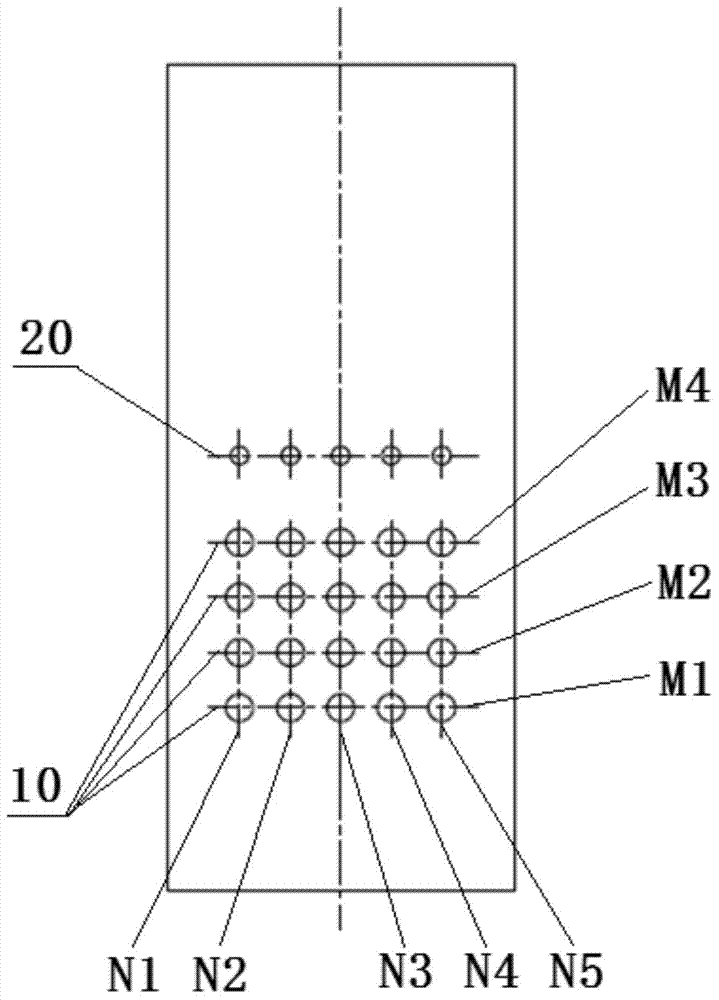
[0074] image 3 It is a schematic diagram of the layout of the burner and the exhaust air nozzle on the boiler body of the wall-type opposed combustion boiler adopting the furnace air staged combustion technology corresponding to the second embodiment of the present invention.

[0075] In the wall-type opposed combustion boiler corresponding to the combustion method of the second embodiment, the front wall and the rear wall of the boiler are arranged as image 3 Shown are a plurality of burners 10 and a plurality of overburning air nozzles 20 disposed above the plurality of burners 10 . Wherein, the burner 10 is specifically a swirl pulverized coal burner.

[0076] like image 3 As shown, in the second embodiment, 20 burners 10 arranged in a matrix are arranged on the front wall of the boiler body, and the 20 burners 10 are divided into four rows and five columns, that is, in the second embodiment, M =4, N=5.

[0077] image 3 Among them, the 20 burners 10 from bottom to ...


PUM


Abstract

The invention discloses a firing method of a wall type opposed firing boiler. A plurality of burners and over-fire air spraying openings located above the multiple burners are arranged on a front wall and a back wall of the wall type opposed firing boiler respectively or are arranged on the front wall of the wall type opposed firing boiler only, and the multiple burners are arranged in a matrix mode, are arranged to be in M lines from bottom to top and are arranged to be in N columns from left to right, wherein the M is an integer larger than or equal to 2, and the N is an integer larger than or equal to 1. The firing method includes the steps of controlling the average excess air coefficient of a main firing area where the multiple burners are located to be smaller than 1, controlling the average excess air coefficient of a firing area between the over-fire air spraying openings and a hearth outlet of the boiler to be larger than 1 so as to achieve in-boiler air grading firing, and controlling the average excess air coefficient of the burners in the first line to be larger than the average excess air coefficient of the burners in the second line to the Mth line. By means of the firing method, the aim of in-time firing can be achieved.

Description

technical field [0001] The invention relates to the field of thermal machinery, in particular to a combustion method for a wall-type opposed combustion boiler. Background technique [0002] Wall-type opposed combustion boilers have been widely used in modern large-scale coal-fired power plants because of their uniform heat load and flue gas temperature distribution along the width of the furnace, which can effectively reduce the thermal deviation between the left and right sides of the heating surface in high-temperature areas. However, the wall-type counter-firing boilers in service in my country are basically imported from foreign advanced combustion technology and then digested and produced. There is a common problem that NOx emissions are seriously exceeding the standard. To solve this problem, air staged combustion technology and low nitrogen burner technology in the furnace are often used. [0003] figure 1 It is a schematic diagram of the principle of the boiler body...

Claims


Application Information

Patent Timeline
Patent Type & Authority Applications(China)
IPC IPC(8): F23N3/00
Inventor 孙树翁张柯李明王雪彩甄晓伟李强
Owner YANTAI LONGYUAN POWER TECH
Why Eureka
Try Eureka