Welded plate frame type heat exchanger

A technology of heat exchangers and welded plates, which is applied in the direction of indirect heat exchangers, heat exchanger types, heat exchanger shells, etc., to achieve the effects of compact structure, reduced possibility of leakage, and expanded use range

Inactive Publication Date: 2015-07-01
GANSU LANPEC TECH
View PDF5 Cites 4 Cited by
  • Summary
  • Abstract
  • Description
  • Claims
  • Application Information

AI Technical Summary

Problems solved by technology

[0005] The purpose of the present invention is to technically improve the design of the existing plate heat exchanger, and to provide a welded plate and frame heat exchanger that solves the problem of thermal expansion and deformation, and is compact in structure and resistant to temperature and pressure.

Method used


Image

  • Welded plate frame type heat exchanger
  • Welded plate frame type heat exchanger
  • Welded plate frame type heat exchanger

Examples


Embodiment 1

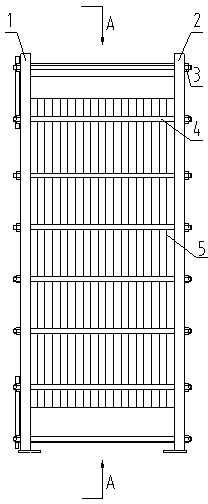
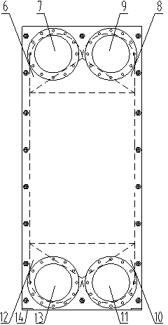
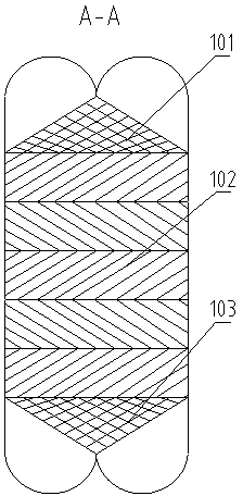
[0030] Embodiment 1, under the condition of single process, refer to the attached Figure 1a , 1b , 1c, cold and hot fluids are arranged in countercurrent, side in and side out, and the flow direction of the fluid in the plate bundle is diagonal flow. A welded plate and frame heat exchanger involved in this embodiment includes welded heat exchange plate bundles 5, the first 1. The second pressing plate 1, 2, the clamping stud nut 4, 3, the inlet and outlet pipe boxes of the cold and hot ends of the plate bundle, the inlet and outlet pipes of the cold and hot medium, and other components.

[0031] The first and second pressing plates 1, 2 and the clamping stud nuts 4, 3 constitute the frame of the heat exchanger. The frame can be made of carbon steel, and its function is to carry the weight of the equipment, carry the bundle of plates, and provide support for it . The hexagonal plate can be made of stainless steel, titanium, nickel-based alloy and other materials, and is welde...

Embodiment 2

[0035] Embodiment 2, under the multi-process working condition, the implementation process of embodiment 2 is basically the same as that of embodiment 1. The difference is that the inlet and outlet ports of the cold and heat medium in embodiment 2 are located on both sides of the first and second compression plates 1 and 2, and the inlet and outlet ports of the cold and heat medium are located on the first and second compression plates 1 and 2. 2 through the via hole 16 is oblong.

Embodiment 3

[0036] Embodiment 3, with reference to attached Figure 2a , 2b , 2c, the implementation process of embodiment 3 is basically the same as the implementation process of embodiment 1. The difference is that the hot and cold fluid inlet and outlet connecting pipes of embodiment 2 are located on the upper and lower sides of the plate bundle, and the opening position of the connecting pipe is located on the upper side of the pipe box round arch, so there is no need to set openings on the first and second pressing plates 1 and 2. The holes allow the hot and cold fluids to enter the tube box straight up and down, which can get better heat exchange effect.


PUM


Abstract

Disclosed is a welded plate frame type heat exchanger. The welding plate frame type heat exchanger comprises a welded heat exchange plate bundle, plate bundle cold and hot end headers and cold and hot medium inlet and outlet connecting tubes; a first pressing plate, a second pressing plate and clamping bolts and nuts form a frame in a space structure; the heat exchange plate bundle is mounted inside the frame; the first pressing plate and the second pressing plate are pressed through the clamping bolts and nuts and fixedly welded with the heat exchange plate bundle; the welded heat exchange plate bundle is connected with the cold and hot medium inlet and outlet connecting tubes through the plate bundle cold and hot end headers to form the welding plate frame type heat exchanger. The welding plate frame type heat exchanger solves the problem of thermal expansion and deformation of plate type heat exchangers during practical work and has the advantages of being capable of changing the plate bundle, heat-resistant, pressure-resistant, high in integral compactness and the like.

Description

technical field [0001] The invention belongs to the technical field of heat exchanger design and manufacture, and in particular relates to a welded plate-and-frame heat exchanger with a compact structure. Background technique [0002] According to different connection methods, plate heat exchangers are mainly divided into detachable plate heat exchangers and fully welded plate heat exchangers. The detachable plate heat exchanger has many advantages such as easy disassembly and maintenance, compact structure, etc., but limited by the physical properties of the gasket, its pressure and temperature resistance is low, its corrosion resistance is weak, and its application range is limited. The fully welded plate heat exchanger has the advantages of high temperature and pressure resistance and strong corrosion resistance. However, due to the constraints of the fully welded structure, its thermal stress is large, it cannot be disassembled for maintenance, and the manufacturing proc...

Claims


Application Information

Patent Timeline
Patent Type & Authority Applications(China)
IPC IPC(8): F28D9/00F28F9/18
Inventor 常春梅侯霄艳胡国栋
Owner GANSU LANPEC TECH
Why Eureka
Try Eureka