Air-tightness detection and nitrogen replacement system and control method for dual-fuel vehicles
An air-tightness detection, dual-fuel vehicle technology, which is applied in the direction of using liquid/vacuum for liquid-tightness measurement, and by measuring the acceleration and deceleration rate of fluids, etc. problem, to achieve the effect of high degree of intelligence, simple detection operation, and high replacement efficiency
- Summary
- Abstract
- Description
- Claims
- Application Information
AI Technical Summary
Problems solved by technology
Method used
Image
Examples
Embodiment 1
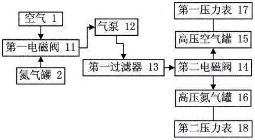
[0061] Such as figure 1 , figure 2 The shown embodiment is an air tightness detection and nitrogen replacement system for a dual-fuel vehicle. The system is connected to the air 1, the nitrogen tank 2 and the vehicle inflation valve 3 respectively; the system includes a high-pressure gas storage device 4 and a pressure-reducing device 5 , pressure reference device 6, inflation device 7, vacuum device 8, first display 9 and controller 10; the gas outlet of the high-pressure gas storage device is connected with the decompression device, and the decompression device is connected with the pressure reference device and the inflation device respectively connection; the controller is electrically connected to the high-pressure gas storage device, the decompression device, the pressure reference device, the inflation device, the vacuum device and the first display;
[0062] Such as image 3 , Figure 5 As shown, the high-pressure gas storage device includes a first solenoid valve ...
Embodiment 2
[0087] Such as Figure 4 , Figure 6 As shown, the vacuum pumping device in Embodiment 2 includes a vacuum pump 29 and a vacuum pressure sensor 30 located on the vacuum pump; both the vacuum pump and the vacuum pressure sensor are electrically connected to the controller; step 200 in Embodiment 1 is replaced by the following steps:
[0088] Step 10, the operator connects the first connector with the automobile inflation valve, the controller controls the third solenoid valve to connect with the high-pressure air tank, the fourth solenoid valve connects the pressure reducing valve and the reference tank, and the fifth solenoid valve connects the pressure reducing valve and the automobile Inflatable valve, the air enters the benchmark tank and the air storage tank of the tested car respectively;
[0089] Step 20, when the pressure values detected by the third, fourth and fifth pressure gauges are all greater than L, the controller controls the connection between the third sol...
Embodiment 3
[0096] In embodiment 3, such as Figure 4 , Figure 6 As shown, a differential pressure sensor 31 is provided between the fourth pressure gauge and the fifth pressure gauge, the output end of the differential pressure sensor is electrically connected to the amplifier 32, and the output end of the amplifier is electrically connected to the controller and the second display 33 respectively; The above step 230 is replaced by the following steps:
[0097] If A<the lower limit of the standard range of the first pressure difference, the controller controls the decompression device to communicate with the high-pressure air tank, and the fourth and fifth solenoid valves communicate with the decompression device respectively;
[0098] When the pressure values detected by the fourth and fifth pressure gauges are both greater than H, the controller controls the connection between the decompression device and the high-pressure air tank, and the connection between the fourth and fifth s...
PUM
 Abstract
Description
Claims
Application Information
 - R&D
- Intellectual Property
- Life Sciences
- Materials
- Tech Scout
- Unparalleled Data Quality
- Higher Quality Content
- 60% Fewer Hallucinations
Browse by: Latest US Patents, China's latest patents, Technical Efficacy Thesaurus, Application Domain, Technology Topic, Popular Technical Reports.
© 2025 PatSnap. All rights reserved.Legal|Privacy policy|Modern Slavery Act Transparency Statement|Sitemap|About US| Contact US: help@patsnap.com


