3D (three-dimensional) microwave resonant cavity comprising DC lead structure

A microwave resonant cavity, 3D technology, used in resonators, material analysis using microwave means, waveguide-type devices, etc., can solve problems such as inability to transmit quantum information, achieve good coupling effect, achieve precise control, and enhance electric field strength. Effect

Inactive Publication Date: 2015-07-01
UNIV OF SCI & TECH OF CHINA
View PDF2 Cites 4 Cited by
  • Summary
  • Abstract
  • Description
  • Claims
  • Application Information

AI Technical Summary

Problems solved by technology

Ordinary electronic circuits cannot transmit quantum information, so we need some special electronic components to achieve this function for us

Method used


Image

  • 3D (three-dimensional) microwave resonant cavity comprising DC lead structure
  • 3D (three-dimensional) microwave resonant cavity comprising DC lead structure
  • 3D (three-dimensional) microwave resonant cavity comprising DC lead structure

Examples


Embodiment Construction

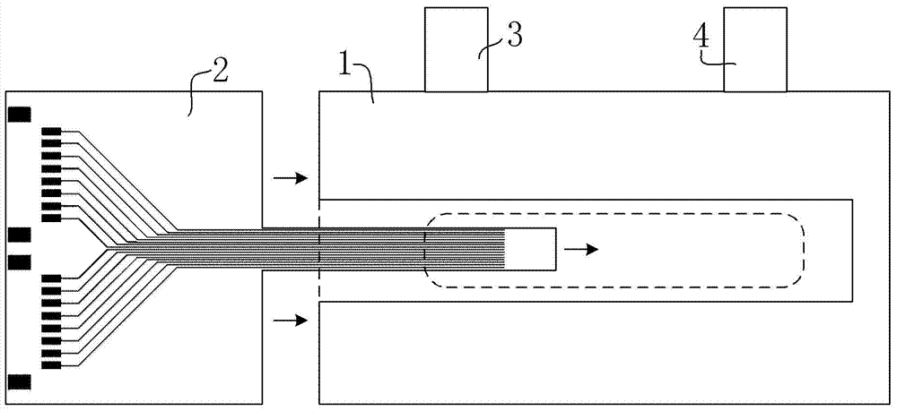
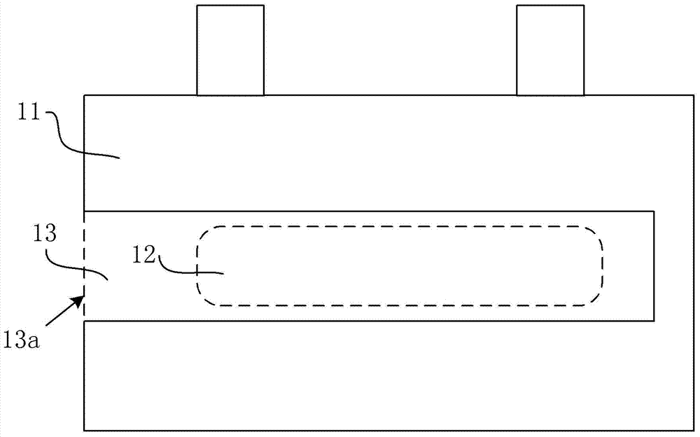
[0026] The present invention proposes a 3D microwave resonant cavity, which includes a cavity body, a circuit board, an input port and an output port. The cavity body is a cuboid, including a shell and a cavity opened inside the shell. The cavity is generally located in the center of the shell. And the extension direction of the cavity is consistent with the length direction of the cavity. The input port and the output port penetrate the housing from the upper portion of the cavity to communicate with the cavity. A slot is opened to the cavity from one side of the cavity along the extending direction of the cavity.

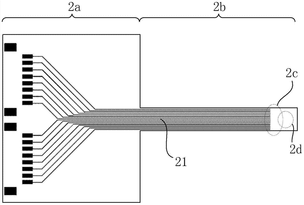
[0027] The circuit board includes an external part and an internal part. The external part has a wider width, and the internal part has a narrower width and is in the shape of a long strip, so that the circuit board as a whole resembles a "T" shape. The insertion portion is insertable into the cavity of the cavity via the slot of the cavity. The insertion part o...


PUM


Abstract

The invention discloses a 3D (three-dimensional) microwave resonant cavity. The 3D microwave resonant cavity comprises a cavity body, a circuit board, an input port and an output port. The cavity body is rectangular and comprises a shell and a hollow cavity provided in the shell. The input port (3) and the output port penetrate the shell from the upper portion of the cavity body (1) and are communicated with the shell. One side of the cavity is provided with a narrow slot along extension direction of the cavity and facing the cavity. The circuit board comprises an external connecting part (2a) and an internal insert part; the external connecting part is wider, the internal insert part is narrower and elongated, and the internal insert part is inserted into the hollow cavity through the narrow slot. The internal insert part comprises a metal lead extending along an insertion direction, a quantum bit device mounting position located at the tail end of the internal insert part and an equipotential connecting line which connects the metal lead and the quantum bit device mounting position. The 3D microwave resonant cavity allows better coupling and allows quantum bit to be precisely controlled.

Description

technical field [0001] The invention relates to a microwave circuit device, in particular to a 3D microwave resonant cavity including a direct current lead structure. Background technique [0002] The semiconductor quantum chip is based on the traditional semiconductor industry, making full use of quantum mechanical effects to realize the core components of high-efficiency parallel quantum computing. Qubits, which can be quantum dots or devices such as superconducting quantum interferometers, are the basic units on quantum chips that can store and manipulate quantum information. However, to complete the quantum computing process, it is also necessary to realize the coupling and data exchange between qubits, as well as the detection and readout of quantum information. Ordinary electronic circuits cannot transmit quantum information, so we need some special electronic components to achieve this function for us. Microwave resonators can excite and transmit microwave photons t...

Claims


Application Information

Patent Timeline
Patent Type & Authority Applications(China)
IPC IPC(8): H01P7/06G01N22/00
Inventor 郭国平孔伟成邓光伟李舒啸李海鸥曹刚肖明
Owner UNIV OF SCI & TECH OF CHINA
Why Eureka
Try Eureka