Reinforcement cage forming machine

A steel cage forming machine and stirrup technology, which is applied to the manufacture of ring nets, other household appliances, household appliances, etc., can solve the problems of high processing cost, large floor area, and low efficiency of steel cage production, and achieve The effect of high production efficiency, small footprint and reasonable structure

Inactive Publication Date: 2015-07-08
海盐海潮水泥制管股份有限公司
View PDF6 Cites 6 Cited by
  • Summary
  • Abstract
  • Description
  • Claims
  • Application Information

AI Technical Summary

Problems solved by technology

[0005] The purpose of the present invention is to overcome the shortcomings of the above-mentioned prior art, and provide a steel cage forming machin

Method used


Image

  • Reinforcement cage forming machine
  • Reinforcement cage forming machine
  • Reinforcement cage forming machine

Examples


no. 1 example

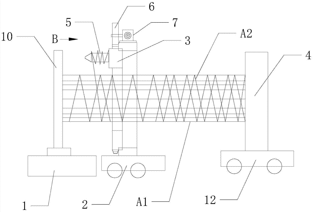
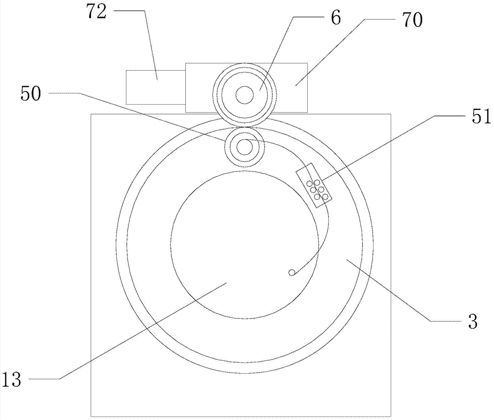
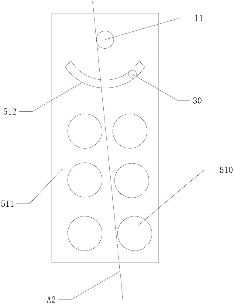
[0020] refer to figure 1 , figure 2 and image 3 , the first embodiment of the present invention provides a steel cage forming machine, comprising a moving frame 4, a rotating frame 3, a fixed frame, a stirrup pay-off device 5, a second moving mechanism 12, and a rotating mechanism 7, on the moving frame 4 The first fixed plate is installed, the moving frame 4 can move linearly along the X-axis direction driven by the second moving mechanism 12 , and the second fixed plate 10 is installed on the fixed frame. In this structure, the moving frame 4 can move linearly along the X-axis direction driven by the second moving mechanism 12 , and the main ribs slide on the second fixed plate 10 . The first fixed disk plate and the second fixed disk plate 10 have the same structure.

[0021] Specifically, the rotating frame 3 is located between the first fixed disk plate and the second fixed disk plate 10 , the stirrup wire releasing device 5 is installed on the rotating frame 3 , and...

no. 2 example

[0030] refer to Figure 4 , Compared with the first embodiment, the difference of the second embodiment of the present invention is that: the rotating mechanism 7 drives the rotating frame 3 to rotate, and the rotating frame 3 and the stirrup pay-off device 5 all include two, two stirrups Pay-off device 5 is installed on two rotating frames 3 respectively, and rotating mechanism 7 can respectively drive two rotating frames 3 to rotate in the opposite direction, and two rotating frames 3 are respectively installed on the both sides of fixed frame and comprises two rotating frames 3 and two rotating frames. A stirrup pay-off device 5, two swivel frames 3 are fixed on the fixed mount, and two stirrup pay-off devices 5 are respectively fixed on the two swivel frames 3. The two stirrup pay-off devices 5 rotate together with the two rotating frames 3 respectively, and the rotating mechanism 7 respectively drives the two rotating frames 3 to rotate in opposite directions. A rotating...


PUM


Abstract

The invention relates to the technical field of building material construction machinery and discloses a reinforcement cage forming machine. The reinforcement cage forming machine comprises a movable rack, rotating racks, a fixed rack, a stirrup pay-off device, a second moving mechanism and a rotating mechanism, a first fixed disc plate is installed on the movable rack, the movable rack can be driven by the second moving mechanism to move in the X-axis direction straightly, and a second fixed disc plate is installed on the fixed rack. According to the reinforcement cage forming machine, the structure is reasonable, a main steel bar is fixed in the machining process, so that a stirrup is wound on the main steel bar spirally, rotating equipment which is large in size is not needed to be used, the fabrication cost of the reinforcement cage forming machine is reduced, the floor area is reduced, so that the reinforcement cage forming machine is low in fabrication cost, small in floor area and high in fabrication efficiency, meanwhile, the two rotating racks are adopted, so that the reinforcement cage forming machine can drive two stirrups to rotate in the positive direction and in the negative direction respectively, the net-shaped stirrups of a spiral structure are formed on the main steel bar, and the external pressure bearing capacity of a finished reinforcement cage is greatly improved.

Description

【Technical field】 [0001] The invention relates to a building material construction machine, in particular to a steel cage forming machine. 【Background technique】 [0002] Generally, the reinforcement cage consists of longitudinally loaded main reinforcement and unidirectional spiral stirrups. The one-way spiral stirrup is mainly used to fix the main reinforcement under longitudinal stress, prevent the main reinforcement from buckling and fix the position of the main reinforcement after being stressed, improve the brittleness of concrete members, form a skeleton with the main reinforcement, ensure the rigidity of the skeleton, and withstand the horizontal load. Shear forces also serve to restrain the concrete within the core to increase bearing capacity. [0003] When the concrete column bears a large axial pressure, due to the large lateral deformation of the core part of the concrete, the one-way spiral stirrup will generate a hoop tension, that is, the core part of the co...

Claims


Application Information

Patent Timeline
IPC IPC(8): B21F31/00
Inventor 林加生
Owner 海盐海潮水泥制管股份有限公司
Why Eureka
Try Eureka