Electromagnetic driven micro ornithopter

An electromagnetic drive, flapping aircraft technology, applied in the field of bionic aircraft, can solve the problems of asymmetric flapping power, low resultant lift force, etc., and achieve the effects of avoiding asymmetry of power, significant resultant lift force, and overcoming the influence of magnetic force with travel distance.

Inactive Publication Date: 2015-07-08
GUANGXI ZHUANG AUTONOMOUS REGION SCI & TECH MUSEUM
View PDF9 Cites 15 Cited by
  • Summary
  • Abstract
  • Description
  • Claims
  • Application Information

AI Technical Summary

Problems solved by technology

[0005] In order to overcome the low resultant lift force caused by the excessively large wing area when flapping upwards, and the asymmetry of the flapping wing power caused by the unstable magnetic force, the present invention provides an electromagnetic structure device for a miniature flapping wing aircraft, which can synchronously control the flapping wing Body electromagnetic coil and wing electromagnetic coil, the power output is stable, and the efficiency is greatly improved

Method used


Image

  • Electromagnetic driven micro ornithopter
  • Electromagnetic driven micro ornithopter
  • Electromagnetic driven micro ornithopter

Examples


Embodiment Construction

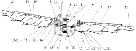
[0024] Attached below Figure 1-5 The present invention is described with embodiment

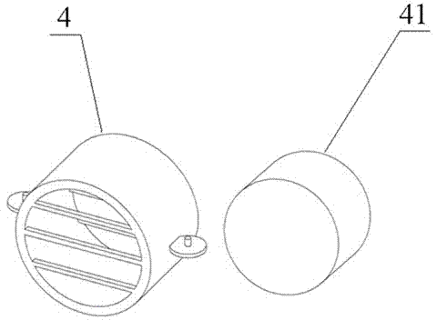
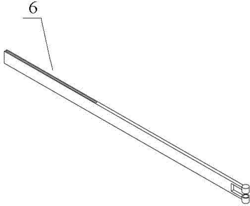
[0025] The AC power supply 101 built in the fuselage 1 inputs alternating current to the upper electromagnetic coil 3 and the lower electromagnetic coil 5. When the forward current is input, the upper electromagnetic coil 3 generates an attractive force on the permanent magnet 41, and the lower electromagnetic coil 5 generates a repulsive force on the permanent magnet 41. , permanent magnet 41 drives permanent magnet body cover 4 to move upwards, and band left movable rod 6, right movable rod 7 move downwards together, and left movable rod 6, right movable rod 7 implicate left-wing skeleton 20, right-wing skeleton 21 to do the action of fluttering down again. When a negative current is input, the upper electromagnetic coil 3 generates repulsion to the permanent magnet 41, and the lower electromagnetic coil 5 generates an attractive force to the permanent magnet 41, and the permanent magnet 4...


PUM


Abstract

An electromagnetic driven micro ornithopter comprises a body, a piston cylinder, an AC power supply, upper and lower electromagnetic coils, a permanent magnet, left and wing motion bars, left wing and right wing rotation shafts, left wing and right wing frameworks and left wing and right wing fins, wherein the piston cylinder and the AC power supply are internally arranged in the frame of the body; the upper and lower electromagnetic coils are arranged at the upper and lower ends of the piston cylinder respectively; the AC power supply is connected with the upper and lower electromagnetic coils; a permanent magnet sleeve is positioned in the middle part of the piston cylinder; the permanent magnet is internally arranged in the permanent magnet sleeve; one end of the left motion pole and one end of the right motion pole are fixed to the left side and the right side of the permanent magnet sleeve and the other end of the left motion pole and the other end of the right motion pole are fixedly to the left wing rotation shaft and the right wing rotation shaft; the left wing rotation shaft and the right wing rotation shaft are fixed to the ends of the left wing framework and the right wing framework; and the right ends of the left wing fins and the left ends of the right wing fins are fixed to the left wing framework and the right wing framework respectively. According to the invention, the upper and lower electromagnetic coils are used for providing magnetic force, so that the flapping power output is doubled. The defect that the magnetic force of a single coil may be influenced by the travel distance is made up and the power output becomes more stable.

Description

technical field [0001] The invention relates to the fields of bionic aircraft and flapping-wing aircraft, in particular to a miniature flapping-wing aircraft driven by electromagnetics. Background technique [0002] The micro-orthopter is a kind of bionic aircraft, which generates lift and thrust to maintain flight by simulating the action of flapping the wings of birds. The current research content mainly focuses on the structure of the flapping wing and the driving device of the flapping wing. [0003] In the research on the structure of the flapping wing, because the lift generated by the flapping wing of the orthopter is asymmetrical in the process of flapping upwards and downwards, downward flapping produces favorable upward lift, while upward flapping produces unfavorable reverse lift. The resulting resultant force of the upward lift force in the flapping cycle is relatively small, and the efficiency is low. In order to make up for the defects, the researchers improv...

Claims


Application Information

Patent Timeline
Patent Type & Authority Applications(China)
IPC IPC(8): B64C33/02
Inventor 秦晓冰李宇飞覃毅峰张加兵盘宝强
Owner GUANGXI ZHUANG AUTONOMOUS REGION SCI & TECH MUSEUM
Why Eureka
Try Eureka