Spiral flow drained water collector for building kitchens

A swirl type and collector technology is applied in the field of drainage collectors for building kitchens, which can solve the problems of easy blockage of pipes, easy drying of floor drains and water seals, and difficult maintenance, etc., and achieves the effect of improving cleanliness and improving drainage capacity.

Active Publication Date: 2015-07-08
贵州群之英屋业科技有限公司
View PDF9 Cites 0 Cited by
  • Summary
  • Abstract
  • Description
  • Claims
  • Application Information

AI Technical Summary

Problems solved by technology

[0002] At present, when floor drains are installed in the drainage kitchens on the same floor of the building, the floors need to be lowered or partially lowered. The pipes under the drainage appliances are easy to block, difficult to overhaul, and the water seal of the floor drains is easy to dry up. The odor and harmful gases in the drainage pipes , insects, etc. are easy to run into the room and affect the living and hygienic environment

Method used


Image

  • Spiral flow drained water collector for building kitchens
  • Spiral flow drained water collector for building kitchens
  • Spiral flow drained water collector for building kitchens

Examples


Embodiment 1

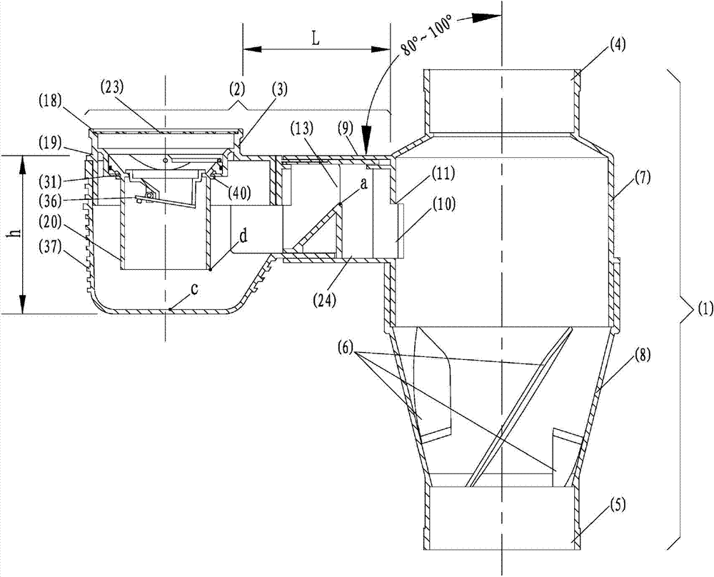
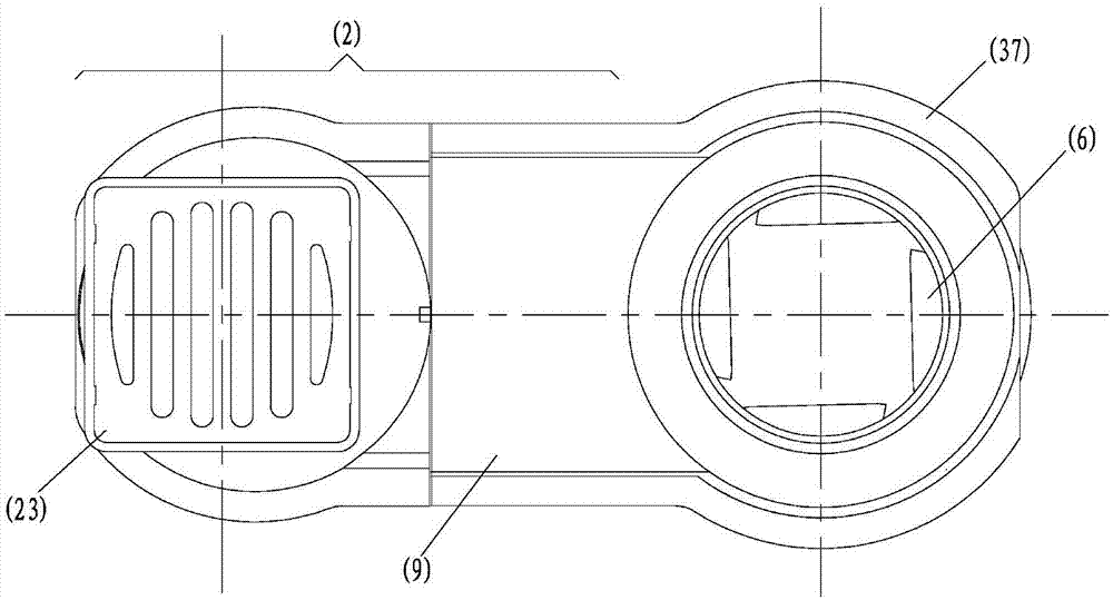
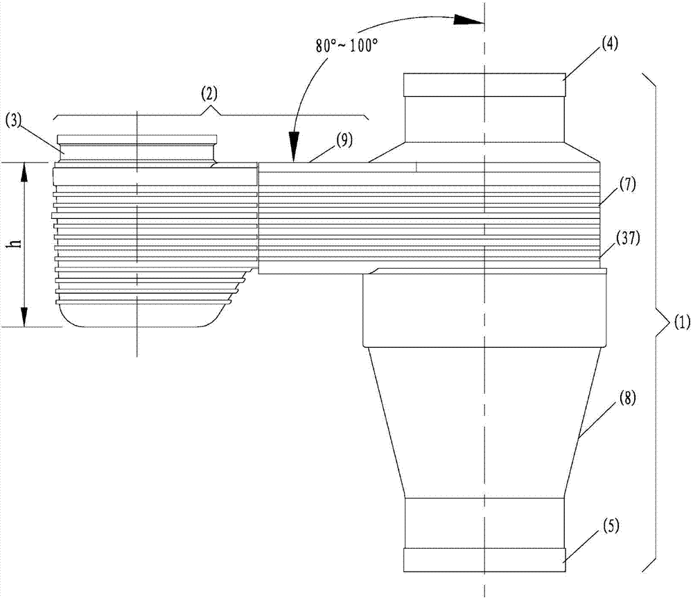
[0029] like figure 1 , 2, 3, and 4, the swirling flow drainage concentrator for building kitchens according to the present invention is composed of a vertical pipe drainage section (1), a horizontal pipe drainage collection section (2) and a water seal member (3). The riser drainage section (1) is connected up and down, and the middle section has expansion, and there are guide vanes (6) in the expansion section. The expansion section is divided into straight section expansion (7) and funnel-shaped expansion (8), straight section expansion (7 ) There is a pipe section with the same outer diameter of 110mm in length at the expansion place, the straight section expansion (7) is located at the upper end of the funnel-shaped expansion (8), below the upper interface (4), and the funnel-shaped expansion (8) is at the lower interface (5) Above; the horizontal pipe drainage collection section (2) is located on one side of the vertical pipe drainage section (1), and the hollow part c...

Embodiment 2

[0031] like Figure 5 As shown, the lower part (20) of the water seal component (20) and the middle part (19) of the water seal component of the building kitchen cyclone drainage collector according to the present invention are not integral components, and the lower end of the middle part (19) of the water seal ( The inner diameter of 31) is larger than the outer diameter of the lower part (20) of the water seal member and smaller than the outer diameter of the upper end (33) of the lower part (20) of the water seal member, and the outer diameter of the upper end (33) of the lower part (20) of the water seal member There is a groove (34) on it, and there is a rubber ring (35) in the groove (34), and the rubber ring (35) is located in the inner wall of the middle part (19) of the water seal member; when it is necessary to overhaul and clean the drainage collection section of the horizontal pipe ( 2), just pull out the lower part (20) of the water seal member from the middle p...

Embodiment 3

[0033] like Figure 5 , 6, the lower part (20) of the water seal member (20) and the middle part (19) of the water seal member of the building kitchen according to the present invention are not integral members, and the lower end of the middle part (19) of the water seal member ( 31) has an inner diameter of 70 mm, the outer diameter of the lower part (20) of the water seal member is 68 mm, the outer diameter of the upper end (33) of the lower part (20) of the water seal member is 86 mm, and the lower end of the middle part (19) of the water seal member ( 31) above table surface and the upper end (33) of the lower part (20) of the water seal member The following table There are two grooves (39) on the lower end (31) of the middle part (19) of the water seal member, the diameter of the groove is 76 mm, and the arc length is 10 mm. The lower part of the water seal member (20) There are 2 bumps (40) on the outer wall of the bump, the outer diameter of the bump (40) is 75mm, ...


PUM


Abstract

A spiral flow drained water collector for building kitchens is formed by a vertical tube water draining segment (1), a transverse tube water draining segment (2) and a water sealing body member (3); a flow guiding blade (6) is arranged in the capacity expanding segment of the vertical tube water draining segment (1); the transverse surface (9) of the transverse tube water draining segment (2) and a below inner wall are planes or approach planes or cambered surfaces; the length of the transverse opening (15) of a collecting segment top channel (13) on the transverse tube water draining segment (2) connected with the vertical tube water draining segment (1) is greater than the length of the vertical opening (16) of the collecting segment top channel (13); and the water sealing body member (3) at one side of the transverse surface (9) is through up and down, a floor drain cover (23) is arranged above the water sealing body member (3), and a distance L from the outer edge of a water sealing body member upper portion (18) to the close outer wall of the vertical tube water draining segment (1) is 40-450mm. The spiral flow drained water collector for building kitchens allows floor drains to be arranged in toilets, kitchens and balconies without any descending floors or slight descending floors in order to solve the water drainage problem on the same floor of a building.

Description

technical field [0001] The invention relates to a drainage collector for building kitchens, in particular to a swirl type drainage collector for building kitchens. Background technique [0002] At present, when floor drains are installed in the drainage kitchens on the same floor of the building, the floors need to be lowered or partially lowered. The pipes under the drainage appliances are easy to block, difficult to overhaul, and the water seal of the floor drains is easy to dry up. The odor and harmful gases in the drainage pipes , small insects, etc. are easy to run into the room and affect the living and hygienic environment. Contents of the invention [0003] The purpose of the present invention is to overcome the existing technical defects, to provide a kitchen that does not need any lowering floor or micro-lowering board when the floor drain is set in the same floor drainage of the building, the pipeline under the drainage device is not easy to block, easy to repa...

Claims


Application Information

Patent Timeline
Patent Type & Authority Applications(China)
IPC IPC(8): E03C1/12E03C1/122E03C1/28E03F5/04
Inventor 林国强程宏伟邱寿华
Owner 贵州群之英屋业科技有限公司
Why Eureka
Try Eureka