
Straight-down backlight source and display device

A backlight, direct-type technology, applied in optics, nonlinear optics, instruments, etc., can solve the problems of direct-type liquid crystal display display effect decline, liquid crystal molecular orientation disorder, display panel 5 deformation, etc., and achieve the distribution of stress points The effect of uniformity, large support range, large force area and range

Inactive Publication Date: 2015-07-08
BOE TECH GRP CO LTD +1
View PDF4 Cites 8 Cited by
  • Summary
  • Abstract
  • Description
  • Claims
  • Application Information

AI Technical Summary

Problems solved by technology

[0004] Usually, the support structure 30 equipped with the direct-type backlight generally adopts a cylindrical or conical structure, and uses the end surface of one end of the cylinder or the end surface of the tapered end of the cone to support the optical film layer 2; since the support surface is a circular support with a small support range On the other hand, during the process of carrying or using the display, the optical film layer 2 and the display panel 5 are prone to vibration after being subjected to external force, and this vibration will cause the deformation of the display panel 5, thereby resulting in a decrease in the display effect of the direct-down liquid crystal display
For example, the deformation of the liquid crystal display panel can cause the relative displacement of the thin film transistor substrate and the color filter substrate, so that the columnar spacer draws out the light-shielding range of the black matrix, scratches the liquid crystal molecules in the pixel, and causes the liquid crystal molecules to be disordered or even more severe light leakage

Method used


Image

  • Straight-down backlight source and display device
  • Straight-down backlight source and display device
  • Straight-down backlight source and display device

Examples


Embodiment Construction

[0023] The following will clearly and completely describe the technical solutions in the embodiments of the present invention with reference to the accompanying drawings in the embodiments of the present invention. Obviously, the described embodiments are only some, not all, embodiments of the present invention. Based on the embodiments of the present invention, all other embodiments obtained by persons of ordinary skill in the art without making creative efforts belong to the protection scope of the present invention.

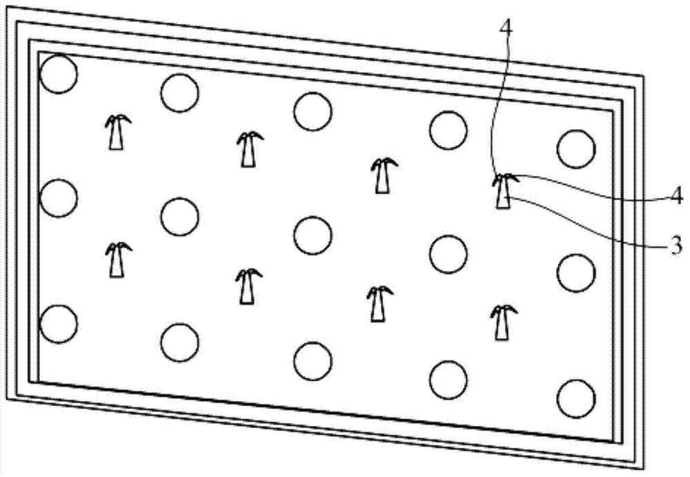
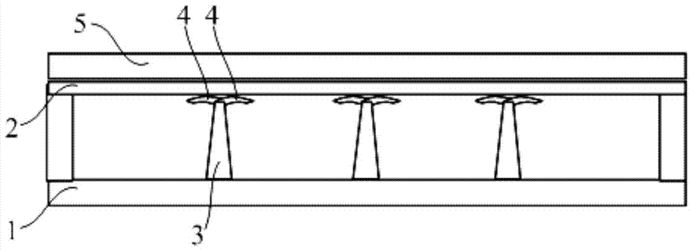
[0024] Such as figure 2 , image 3 , Figure 4b and Figure 4c As shown, the direct-lit backlight provided by the embodiment of the present invention includes a backplane 1 and an optical film layer 2 arranged oppositely, and a support structure 3 between the backplane 1 and the optical film layer 2; the support The structure 3 is supported between the backplane 1 and the optical film layer 2; the first end for supporting the optical film layer 2 in the su...


PUM


Abstract

The invention relates to the technical field of display, and discloses a straight-down backlight source and a display device. The straight-down backlight source comprises a back plate and an optical film which are oppositely arranged, and a supporting structure located between the back plate and the optical film. The supporting structure is supported between the back plate and the optical film, the first end, used for supporting the optical film, in the supporting structure is provided with at least two elastic bending structures, one end of each elastic bending structure is connected with the supporting structure, the other end of each elastic bending structure stretches out of the supporting structure and stretches in the direction away from the axial line of the supporting structure, and the surface, facing the optical film, of each elastic bending structure abuts against the optical film. By the adoption of the straight-down backlight source, the stressed area of a display panel receiving supporting force and used in cooperation with the straight-down backlight source is larger, stress points are more evenly distributed, and therefore deformation of the display panel used in cooperation with the straight-down backlight source can be effectively avoided.

Description

technical field [0001] The invention relates to the field of display technology, in particular to a direct-type backlight source and a display device. Background technique [0002] Liquid crystal displays have been widely used in electronic information products such as mobile phones, notebooks, and monitors. Existing liquid crystal displays mainly include a liquid crystal display panel and a backlight module for providing a surface light source for the liquid crystal display panel. At present, the direct-type backlight and the side-type backlight are commonly used as two types of backlight modules, each of which has advantages and disadvantages. The direct-lit backlight has better advantages in picture control technology and lower cost. [0003] Such as figure 1 As shown, generally, a direct-type backlight includes a backplane 1, a light source 10, a plurality of support structures 30, and an optical film layer 2, wherein the backplane 1 is arranged opposite to the optica...

Claims


Application Information

Patent Timeline
Patent Type & Authority Applications(China)
IPC IPC(8): G02F1/13357
CPCG02F1/133608
Inventor 崔晓鹏王俊伟刘家荣
Owner BOE TECH GRP CO LTD
Learn More