
Cell splitting device and cell splitting method

A technology of slivers and transmission devices, which is applied in the direction of sustainable manufacturing/processing, electrical components, climate sustainability, etc., can solve the problems of reduced efficiency, high fragmentation rate, and difficult industrial production, so as to ensure accuracy, improve efficiency, The effect of reducing fragmentation rate

Inactive Publication Date: 2015-07-08
HANS LASER TECH IND GRP CO LTD
View PDF10 Cites 19 Cited by
  • Summary
  • Abstract
  • Description
  • Claims
  • Application Information

AI Technical Summary

Problems solved by technology

The main function of the two is to break the solar cell, that is, to split a cell into 2 pieces, or to split a cell into 4 pieces, but not to split a battery into multiple pieces. column, which reduces its efficiency, and the fragmentation rate is high, which is not easy for industrial production; at the same time, there is a further existence: automatic loading and unloading can only be realized by manipulator and vacuum suction, which is very inconvenient to use

Method used


Image

  • Cell splitting device and cell splitting method
  • Cell splitting device and cell splitting method
  • Cell splitting device and cell splitting method

Examples


Embodiment Construction

[0029] In order to facilitate the understanding of the present invention, the present invention will be described more fully below with reference to the associated drawings. Preferred embodiments of the invention are shown in the accompanying drawings. However, the present invention can be embodied in many different forms and is not limited to the embodiments described herein. On the contrary, these embodiments are provided to make the understanding of the disclosure of the present invention more thorough and comprehensive.

[0030] It should be noted that when an element is referred to as being “fixed” to another element, it can be directly on the other element or there can also be an intervening element. When an element is referred to as being "connected to" another element, it can be directly connected to the other element or intervening elements may also be present.

[0031] Unless otherwise defined, all technical and scientific terms used herein have the same meaning as...


PUM


Abstract

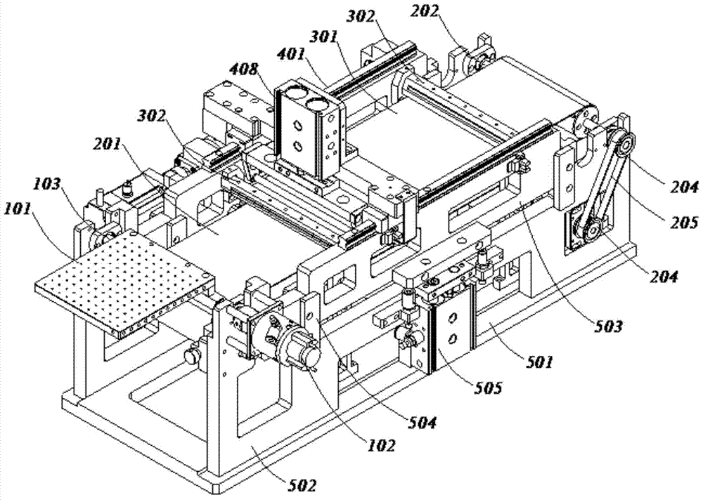
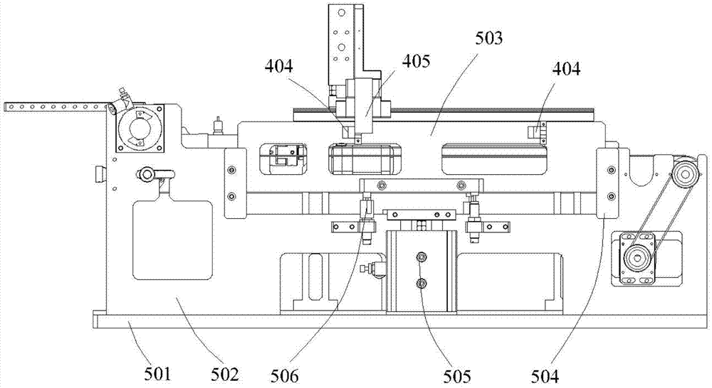
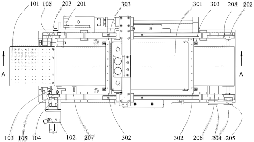
The invention relates to the technical field of crystalline silicon cell manufacturing, and discloses a cell splitting device and a cell splitting method. The device comprises a device body, a feeding device and a flexible belt conveying device which are arranged on the device body in sequence, a lifting device mounted on the device body and disposed at one side of the flexible belt conveying device, a flexible belt coating device mounted on the lifting device and disposed on the upper end of the flexible belt conveying device, and a roller rolling device mounted on the lifting device and disposed on the upper end of the flexible belt coating device. A pressing device for driving the roller rolling device to press the flexible belt coating device and a linear moving device for driving the roller rolling device to move along the conveying direction of the flexible belt conveying device are mounted on the roller rolling device. According to the invention, a cell is coated with two layers of flexible belts and is rolled by the roller rolling device, so that the cell is not broken or moved, the efficiency of cell splitting is improved, and the fragmentation rate is reduced.

Description

technical field [0001] The present invention relates to the technical field of crystalline silicon cell manufacturing, and more specifically, to a splitting device and a splitting method for splitting a thin crystalline silicon cell into multiple rows of sub-cells. Background technique [0002] In the manufacture of crystalline silicon cells, splitting the cells to form grid cells is a pre-process for parallel and series welding of grid cells. In the prior art, the sheets are generally manually broken and placed in a row, which has defects such as low efficiency and high fragmentation rate. Therefore, the production of this kind of linear PV cells can only stay in the experimental and trial production stage, which affects its industrialization. schedule. [0003] Although the patent No. 201210292493.1 discloses an automatic splitting device for cells, which has a bracket, a vacuum suction mechanism for vacuum adsorption of solar cells, a gear transmission mechanism, a power...

Claims


Application Information

Patent Timeline
IPC IPC(8): H01L21/78H01L31/18
CPCH01L21/78H01L31/1804Y02P70/50
Inventor 汤子文黄东海张宏里谢建徐波陈明金段军兵高云峰
Owner HANS LASER TECH IND GRP CO LTD
Learn More