
Heat transfer structure and manufacturing method thereof

A manufacturing method and technology of thermal conductivity, applied in semiconductor/solid-state device manufacturing, electrical components, electric solid-state devices, etc., can solve problems such as low thermal conductivity, low thermal conductivity of TIM material 50, low thermal conductivity of TIM material, etc., to achieve Effect of increasing thermal conductivity, eliminating or minimizing interfacial thermal resistance

Active Publication Date: 2017-11-14
恩特日安
View PDF7 Cites 0 Cited by
  • Summary
  • Abstract
  • Description
  • Claims
  • Application Information

AI Technical Summary

Problems solved by technology

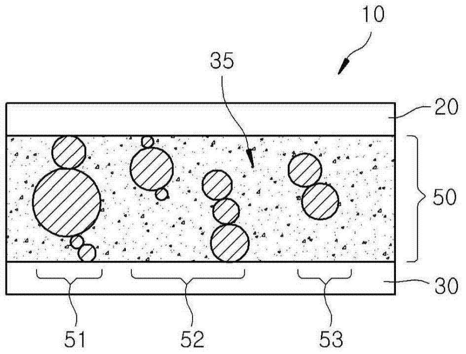
[0008] Further, as figure 1 As shown, the thermally conductive materials 52 and 53 can be distributed so as not to be in contact with the semiconductor chip 20 or the heat sink assembly 30, which also results in the low thermal conductivity of the traditional TIM material 50.
[0009] Another reason for the low thermal conductivity of conventional TIM materials may be that the thermally conductive materials 51 to 53 are formed to be in point contact with the semiconductor chip 20 and / or the heat sink assembly 30, such as figure 1 shown
In the case where the heat generated in the semiconductor chip 20 is transferred to the heat sink assembly 30 via point contact, due to the point contact (for example, the point contact between the semiconductor chip 20 and the thermally conductive material 51 and the point between two adjacent thermally conductive materials Contact, etc.) makes the area smaller and thus the thermal conductivity becomes lower

Method used


Image

  • Heat transfer structure and manufacturing method thereof
  • Heat transfer structure and manufacturing method thereof
  • Heat transfer structure and manufacturing method thereof

Examples


no. 1 example

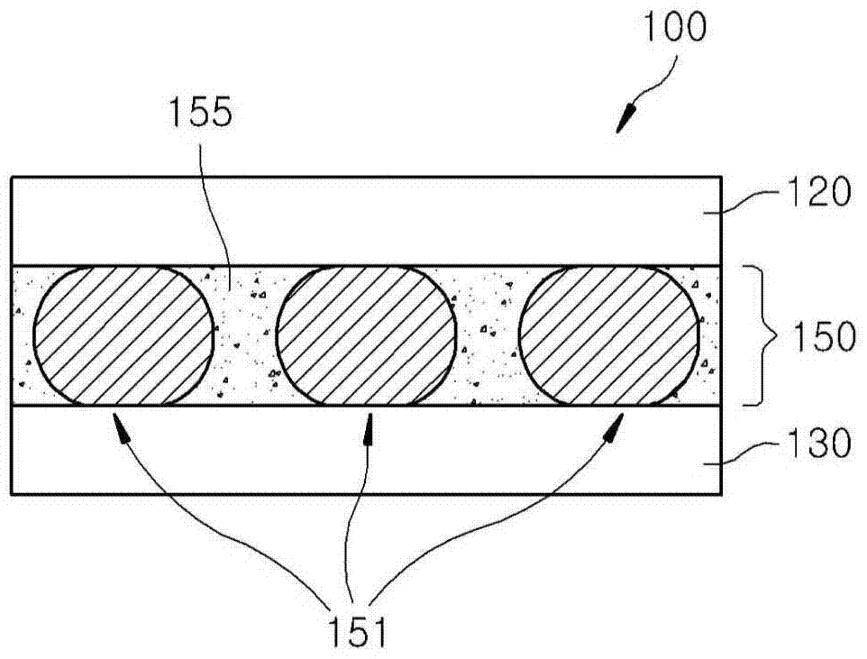
[0056] In the heat transfer structure 100 with the configuration of the direct heat path according to the first embodiment of the present invention, the heat generated in the first object 120 passes through the heat conductive material 151 consisting of only one layer and is transferred to the second object 130 . In this case, an interfacial thermal resistance on a path through which heat passes may be smaller than an interfacial thermal resistance when heat passes through a plurality of thermally conductive materials connected to each other in series. Therefore, according to the first embodiment of the present invention, thermal conductivity higher than that of conventional TIM materials can be obtained.

[0057] In addition, since at least one thermally conductive material 151 is uniform in size, in the case where any one of the thermally conductive materials 151 is in contact with the first object 120 and the second object 130, the remaining thermally conductive material 15...


PUM

PropertyMeasurementUnit
melting pointaaaaaaaaaa

Abstract

The present invention provides a heat transfer structure, which includes: a first object; a second object; and a heat transfer bonding material arranged between the first object and the second object to be connected with the first object or the second object at least one contact of . The heat transfer adhesive material includes: a resin; and at least one heat conductive material, and the at least one heat conductive material is distributed by being dispersed in the resin, and comes into surface contact with at least one of the first object or the second object.

Description

[0001] related application [0002] This application is based on and claims the priority of Korean Patent Application No. 10-2014-0001586 filed on January 7, 2014 and Korean Patent Application No. 10-2014-0001587 filed on January 7, 2014, incorporated by reference Its disclosure is incorporated herein in its entirety. technical field [0003] The present invention relates to a heat transfer structure and a manufacturing method thereof, in particular to a method capable of arranging a plurality of thermally conductive materials with uniform sizes in a layer between a semiconductor chip and a heat dissipation component, and combining the plurality of thermally conductive materials with the semiconductor chip and the heat dissipation assembly. A heat transfer structure and a manufacturing method thereof in which heat dissipation components are in surface contact to more effectively dissipate heat generated by internal components such as semiconductor chips. Background technique...

Claims


Application Information

Patent Timeline
Patent Type & Authority Patents(China)
IPC IPC(8): H01L23/373H01L23/367H01L21/48
CPCH01L23/3737H01L2224/11H01L2924/0002H01L23/3736H01L2924/00
Inventor 郑世泳
Owner 恩特日安
Learn More