Laser module
A technology of optical modules and lasers, which is applied in the field of optical modules, can solve problems such as performance degradation and increased heat generation of optical modules, and achieve the effects of improving alignment accuracy and suppressing light loss
- Summary
- Abstract
- Description
- Claims
- Application Information
AI Technical Summary
Problems solved by technology
Method used
Image

Examples
Embodiment approach 1
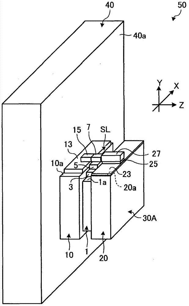
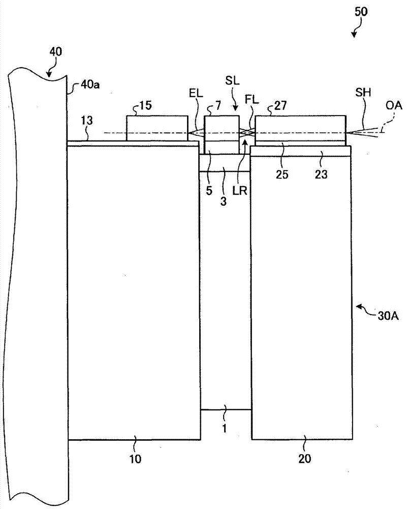
[0027] figure 1 It is a perspective view schematically showing an example of the optical module of the present invention. The optical module 50 shown in this figure includes: a base 30A divided into three blocks of a first block 1 , a second block 10 , and a third block 20 ; and a substrate 40 .
[0028] A thin plate-shaped stress buffering member 3 is fixed to the upper surface 1a of the first block 1 with a bonding material (not shown). The heat sink 5 is fixed on the stress buffering member 3 with a bonding material (not shown), and the laser medium 7 is fixed and mounted on the heat sink 5 with a bonding material (not shown). The first block 1 is a plate-shaped member having two side surfaces perpendicular to the optical axis of the laser medium 7, and is made of, for example, a metal material or an alloy material. The stress buffering member 3 relieves thermal stress caused by the difference in linear expansion coefficient between the first block 1 and the heat sink 5 ....
Embodiment approach 2
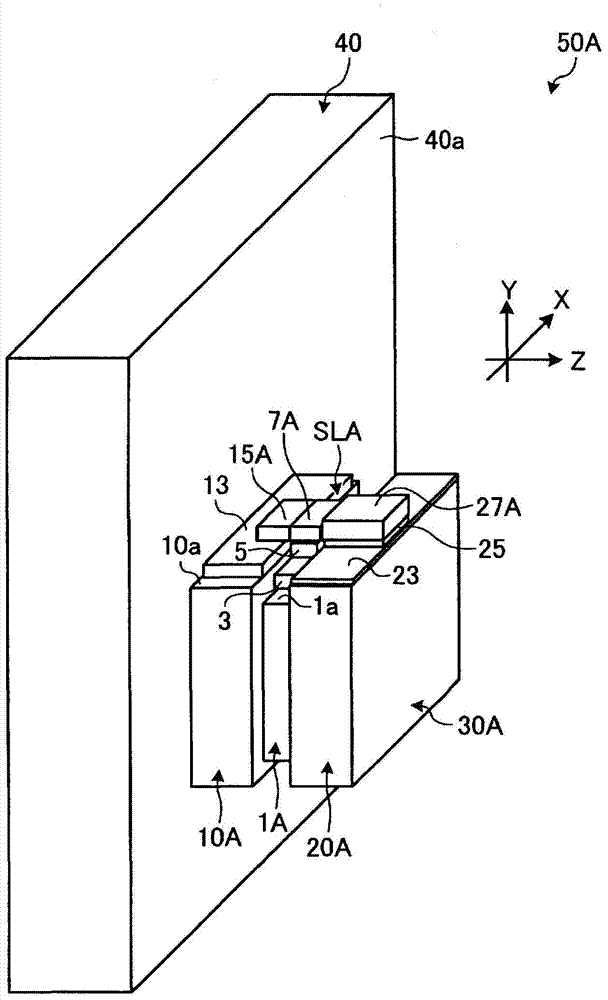
[0045] The optical module of the present invention can also form multiple emitters. When forming a plurality of emitters, for example, a first block on which a laser medium having a plurality of optical waveguides is mounted on an upper surface, a second block on which a plurality of excitation light sources are mounted on an upper surface, and The second of the third block of one wavelength conversion element on which a plurality of wavelength conversion elements or a plurality of optical waveguides are formed is fixed on the substrate, and the remaining two blocks are fixed on this block in a predetermined arrangement.
[0046] image 3 It is a perspective view schematically showing an example of an optical module in which a plurality of emitters are formed. The figure shows optical module 50A, except replacing the figure 1 The first block 1, the second block 10, and the third block 20 shown have the first block 1A, the second block 10A, and the third block 20A, and have t...
Embodiment approach 3
[0051] In the optical module of the present invention, a light guide that receives excitation light from an external light source and emits it to the laser medium side may be used as the excitation light source for the laser medium.
[0052] Figure 4 It is a perspective view schematically showing an example of an optical module having a light guide as an excitation light source of a laser medium. The optical module 150 shown in this figure, in addition to including the replacement figure 1 The second block 10 shown has a base 30B of the second block 110, and the bottom surface of the second block 110 is fixed on the substrate 40, and has the same figure 1 The light module 50 shown has the same structure. for Figure 4 Among the components shown are the figure 1 The same parts as the constituent parts shown are given the same figure 1 The same reference numerals as used in , and description thereof will be omitted.
[0053] A light guide 113 is fixed to the upper surface...
PUM
 Abstract
Description
Claims
Application Information
 - R&D
- Intellectual Property
- Life Sciences
- Materials
- Tech Scout
- Unparalleled Data Quality
- Higher Quality Content
- 60% Fewer Hallucinations
Browse by: Latest US Patents, China's latest patents, Technical Efficacy Thesaurus, Application Domain, Technology Topic, Popular Technical Reports.
© 2025 PatSnap. All rights reserved.Legal|Privacy policy|Modern Slavery Act Transparency Statement|Sitemap|About US| Contact US: help@patsnap.com