A rotor for an electric motor or generator

A motor and generator technology, applied in the field of rotors, can solve the problem of high magnetic flux leakage

Active Publication Date: 2015-07-08
PROTEAN ELECTRIC LIMITED
View PDF3 Cites 4 Cited by
  • Summary
  • Abstract
  • Description
  • Claims
  • Application Information

AI Technical Summary

Problems solved by technology

However, this design for an inner rotor that utilizes a V-shaped magnet configuration is not suitable for motors with outer rotors, where the rotor typically does not have enough radial space to utilize a one-piece rotor iron components to accommodate the angularly offset rare earth magnets used in the inner rotor design
Also, for these designs, flux leakage can be relatively high

Method used


Image

  • A rotor for an electric motor or generator
  • A rotor for an electric motor or generator
  • A rotor for an electric motor or generator

Examples


Embodiment Construction

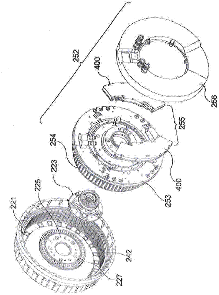
[0017] figure 1 and figure 2 An electric motor assembly is shown with an electric motor having a rotor according to the invention, wherein the electric motor assembly includes built-in electronics and is configured for use as an in-wheel or in-wheel motor configured to accommodate a wheel. But the invention can be incorporated into any form of electric motor. The electric motor can also be designed as a generator.

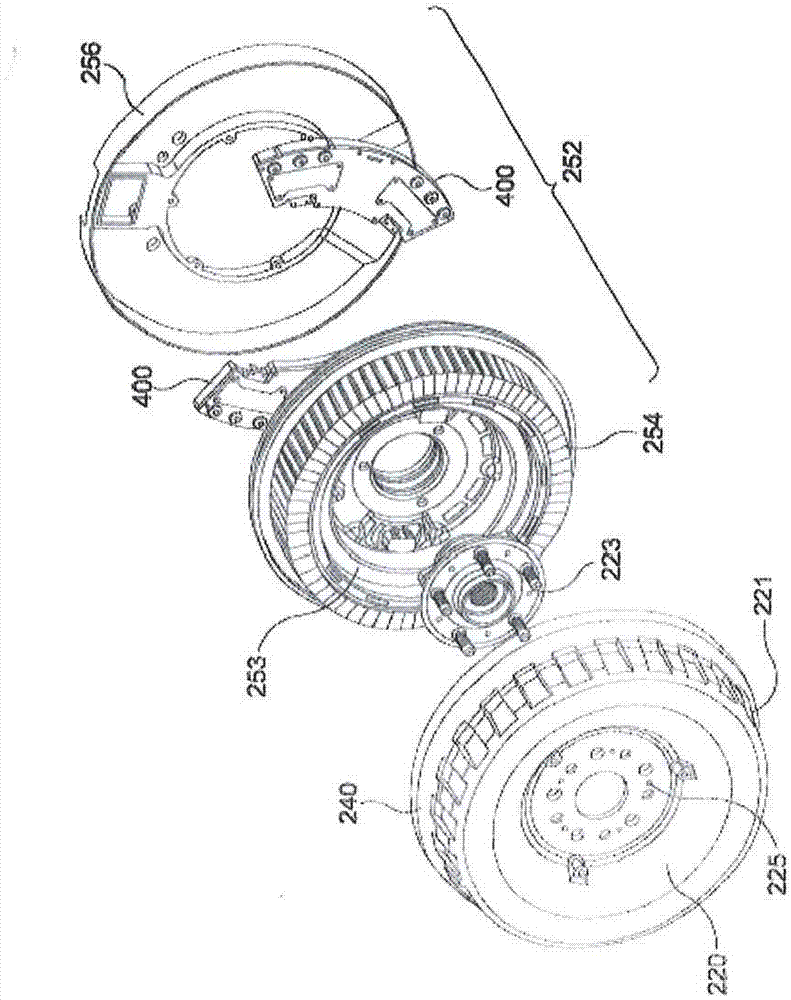
[0018] figure 2 Shown from the opposite side with the figure 1 An exploded view of the same components.

[0019] Such as figure 1 and figure 2 As shown, in order to implement the present embodiment, the in-wheel motor includes a stator 252 and a rotor 240 . The stator 252 preferably includes a main stator frame 253 containing cooling fins, a doubler coil 254 and an electronics module 255 mounted within the rear of the main stator frame 253 to drive the coil. Coils 254 are formed on the stator tooth laminations to form the coil windings. The stator teeth...


PUM


Abstract

An external rotor for an electrical motor or generator (e.g. a wheel motor) has poles, each comprising a pair of rare earth permanent magnets 30 inclined towards each other in V formation. Soft ferromagnetic elements 32, 33 are arranged to retain the magnets, element 32 being mounted by its outer surface 35 to the inner rim of the rotor by means of adhesive or mechanical connectors, magnet surfaces 36 of each of the magnet pairs being adhesive mounted in V formation on the inclined inner surface of the element 32. Wedge shaped elements 33 are secured to the opposite face 37 of the magnets 30, and are arranged with respect to adjacent elements with an air gap 34 between respective end potions of the elements 33. Surface 38 of the element 33 forms the pole surface. The method of assembly may comprise magnetically holding the elements 33 to a former, securing the magnets 30 thereto, attaching the element 32 to the other faces of the magnets and subsequently mounting the circumferential potion of the rotor over element 32. The gap 34 may comprise a low reluctance material and the V assembly may be replaced by a single C shaped magnet.

Description

technical field [0001] The invention relates to rotors, in particular rotors for electric motors or generators. Background technique [0002] Motors work as follows, current carrying wires will experience a force in the presence of a magnetic field. When the current-carrying wire is placed perpendicular to the magnetic field, the force acting on the current-carrying wire is proportional to the magnetic flux density of the magnetic field. Typically, the force acting on a current-carrying wire is generated in an electric motor in the form of torque. [0003] Examples of known types of motors include induction motors, brushless permanent magnet motors, switched reluctance motors and synchronous slip ring motors, which have a rotor and a stator as is well known to those skilled in the art. [0004] Since the force acting on the current-carrying wires and thus the torque on the motor is proportional to the magnetic field flux density, it is best to use a motor with as high a to...

Claims


Application Information

Patent Timeline
Patent Type & Authority Applications(China)
IPC IPC(8): H02K1/27H02K15/03
CPCH02K1/2766H02K1/2786H02K7/14H02K1/2791B60L15/20B60L2220/14B60L2220/44B60L2240/423B60L2240/425B60L2220/50Y02T10/72B60L50/51Y02T10/64Y02T10/70H02K1/28H02K15/03H02K21/22
Inventor A·弗雷泽D·考斯提克佩科维奇G·苏里亚库马B·C·梅克罗N·J·贝克尔S·杨
Owner PROTEAN ELECTRIC LIMITED
Why Eureka
Try Eureka