Hollow radial-magnetic-field permanent magnet opposite-rotating double-rotor compensation pulse electric generator

A radial magnetic field and compensation pulse technology, applied in electrical components, electromechanical devices, etc., can solve the problems of increasing the system volume, parallel current synchronization, doubling, etc., to achieve a simple motor control system, reduced volume, and reduced torque impact Effect

Active Publication Date: 2015-07-08
HARBIN INST OF TECH
View PDF4 Cites 7 Cited by
  • Summary
  • Abstract
  • Description
  • Claims
  • Application Information

AI Technical Summary

Problems solved by technology

However, two motors increase the volume of the system, the two current output ports, and the switch control device will also double, and it will also bring about the problem of current parallel synchronization

Method used


Image

  • Hollow radial-magnetic-field permanent magnet opposite-rotating double-rotor compensation pulse electric generator
  • Hollow radial-magnetic-field permanent magnet opposite-rotating double-rotor compensation pulse electric generator

Examples


specific Embodiment approach 1

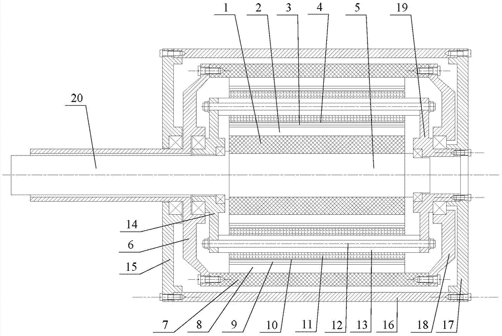
[0029] Specific implementation mode one: the following combination figure 1 Describe this embodiment, the hollow radial magnetic field permanent magnet counter-rotating dual-rotor compensation pulse generator described in this embodiment includes an outer rotor, an inner rotor, a stator, an inner rotor shaft 5, an outer rotor left end cover 6, and a stator left end cover 14 , the left end cover 15 of the casing, the casing 16, the right end cover 17 of the casing, the right end cover 18 of the outer rotor, the right end cover 19 of the stator and the outer rotor shaft 20,

[0030] The outer rotor includes an outer rotor yoke 7, an outer rotor permanent magnet 8, an outer rotor compensation cylinder 9 and an outer rotor bandage 10,

[0031] The inner rotor includes the inner rotor yoke 1, the inner rotor permanent magnet 2, the inner rotor compensation cylinder 3 and the inner rotor bandage 4, the stator package

[0032] Including stator armature winding 11, stator connector 1...

specific Embodiment approach 2

[0040] Specific Embodiment 2: In this embodiment, Embodiment 1 is further described. The inner rotor permanent magnet 2 and the outer rotor permanent magnet 8 are Halbach permanent magnet array structures.

specific Embodiment approach 3

[0041] Embodiment 3: This embodiment further describes Embodiment 1 or 2. The air-gap magnetic density generated by the inner rotor permanent magnet 2 and the outer rotor permanent magnet 8 is radial.


PUM


Abstract

The invention discloses a hollow radial-magnetic-field permanent magnet opposite-rotating double-rotor compensation pulse electric generator, and belongs to the technical field of pulse electric generators. The hollow radial-magnetic-field permanent magnet opposite-rotating double-rotor compensation pulse electric generator aims at solving the problems that two electric generators are arranged in parallel at present and synchronously and oppositely rotate to counteract electromagnetic torque impacting generated during discharging of the pulse electric generators, and the sizes of the electric generators are enlarged accordingly. The hollow radial-magnetic-field permanent magnet opposite-rotating double-rotor compensation pulse electric generator comprises an outer rotor, an inner rotor and a stator. An inner rotor shaft and an outer rotor shaft are coaxial, the outer rotor, the stator and the inner rotor are sequentially and coaxially arranged from outside to inside, an outer air gap is formed between the outer rotor and the stator, and an inner air gap is formed between the stator and the inner rotor. An inner rotor yoke is fixed to the inner rotor shaft, an inner rotor permanent magnet is arranged on the outer circumference surface of the inner rotor yoke, and an inner rotor compensation cylinder and an inner rotor bandage are sequentially arranged on the outer circumference surface of the inner rotor permanent magnet; the magnetic field formed by the inner rotor permanent magnet and the magnetic field formed by the outer rotor permanent magnet are intersected with one side of a stator armature winding. The hollow radial-magnetic-field permanent magnet opposite-rotating double-rotor compensation pulse electric generator is a compensation pulse electric generator.

Description

technical field [0001] The invention relates to a hollow radial magnetic field permanent magnet counter-rotating dual-rotor compensation pulse generator, which belongs to the technical field of pulse generators. Background technique [0002] High-power pulse power supply can provide short-term strong pulse current, which is an important part of electromagnetic emission. The pulse generator based on inertial energy storage is a special synchronous generator, which greatly reduces the internal inductance of the armature winding by using the compensation principle and the magnetic flux compression principle, thereby obtaining a pulse current with a very high amplitude. Strong application potential. [0003] There are two main excitation methods for pulse generators: electric excitation and permanent magnet excitation. Because electric excitation requires brushes, the structure of the motor is complex, and the wear and ablation of the brushes will also reduce the reliability o...

Claims


Application Information

Patent Timeline
Patent Type & Authority Applications(China)
IPC IPC(8): H02K16/02
CPCH02K16/02
Inventor 吴绍朋王少飞崔淑梅
Owner HARBIN INST OF TECH
Why Eureka
Try Eureka