Eureka AIR delivers breakthrough ideas for toughest innovation challenges, trusted by R&D personnel around the world.

LED drive control circuit for switch dimming

A technology of LED drive and control circuit, applied in the direction of electric lamp circuit layout, light source, electric light source, etc., can solve the problems of inability to adjust the output current size, fixed output current, etc., and achieve stable and reliable performance, small size and wide application range. Effect

Active Publication Date: 2015-07-08
南京典润电气有限公司
View PDF5 Cites 3 Cited by
  • Summary
  • Abstract
  • Description
  • Claims
  • Application Information

AI Technical Summary

Problems solved by technology

Although the current LED drive power supply has achieved constant current output, the disadvantage is that the output current is fixed and the output current cannot be adjusted.

Method used


Image

  • LED drive control circuit for switch dimming
  • LED drive control circuit for switch dimming
  • LED drive control circuit for switch dimming

Examples


Embodiment 1

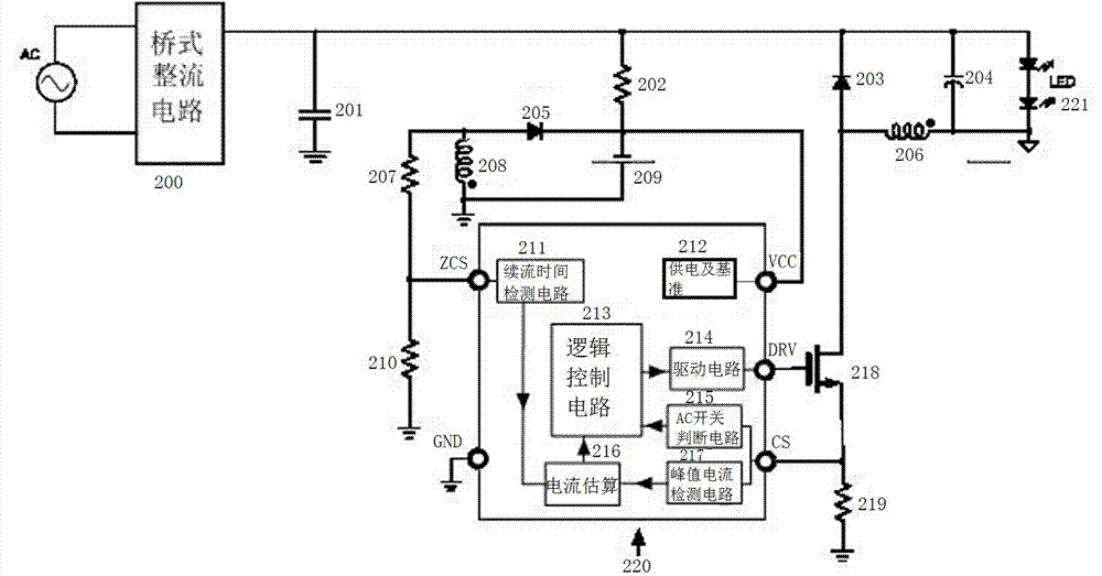
[0016] Such as figure 1 A switch dimming LED drive control circuit shown includes a bridge rectifier circuit 200 and an LED drive control circuit 220, and the bridge rectifier circuit 200 is connected in parallel with a high-voltage filter capacitor 201, a first resistor 202, and an LED drive circuit 221, respectively. , wherein the first resistor 202 is connected in series with the second resistor 207, the second resistor 207 is grounded through the third resistor 210, and the second resistor 207 and the third resistor 210 are connected to the LED drive control circuit 220, so The LED drive control circuit 220 is connected to the gate of the power transistor 218 , and the source of the power transistor 218 is grounded through the fourth resistor 219 . The bridge rectifier circuit 200 is connected in parallel with the energy storage capacitor 204 .

[0017] The LED drive control circuit 220 includes a peak current detection circuit 217, a current estimation circuit 21...


PUM


Abstract

The invention discloses an LED drive control circuit for switch dimming. The LED drive control circuit comprises a bridge rectifier circuit and an LED drive control circuit unit, wherein the bridge rectifier circuit is connected with a high-voltage filter capacitor, a first resistor and an LED drive circuit in parallel, the first resistor is connected with a second resistor in series, the second resistor is grounded through a third resistor, the second resistor is connected with the third resistor through the LED drive control circuit unit, the LED drive control circuit unit is connected with the grid of a power tube, and the source of the power tube source is grounded through a fourth resistor. The LED drive control circuit for switch dimming has low overall plan cost, and is small in size, simple and practical in structure, stable and reliable in working performance and wide in application range.

Description

technical field [0001] The invention relates to an intelligent LED dimming circuit, in particular to an LED driving control circuit and its driving circuit structure for detecting a mains switch to realize different output currents. Background technique [0002] In recent years, LED lighting has been widely used due to its advantages of high efficiency, energy saving, environmental protection and long life. In different usage occasions, the requirements for the brightness of LED lamps are also different. Although the current LED drive power supply has achieved constant current output, the disadvantage is that the output current is fixed and the output current cannot be adjusted. Contents of the invention [0003] The object of the present invention is to provide an on-off dimming LED drive control circuit, the overall scheme of which has low cost, small volume, simple and practical structure, stable and reliable working performance, and wide application range. [0004] I...

Claims


Application Information

Patent Timeline
Patent Type & Authority Applications(China)
IPC IPC(8): H05B37/02
Inventor 孙菊根田剑彪孙文浩
Owner 南京典润电气有限公司
Why Eureka
Eureka Blog
Learn More