
Electromagnetic positioning system and selection method for three-dimensional image view angle of electromagnetic positioning system

An electromagnetic positioning and electromagnetic technology, which is applied in the fields of medical science, acoustic wave diagnosis, infrasonic wave diagnosis, etc., can solve the problems that the ultrasonic system cannot be imaged, the detection accuracy is low, and the positioning of the device cannot be involved, so as to achieve intelligent processing capabilities and high safety , easy to use and reliable effect

Inactive Publication Date: 2015-07-15
UNITED IMAGING SYST BEIJING CO LTD
View PDF15 Cites 6 Cited by
  • Summary
  • Abstract
  • Description
  • Claims
  • Application Information

AI Technical Summary

Problems solved by technology

[0006] The purpose of the present invention is to provide an electromagnetic positioning system and a method for selecting a three-dimensional image angle of view to solve the problem that in the existing medical detection and treatment process, the ultrasound system cannot be imaged according to the doctor's angle of view, and the diagnosis and treatment process mainly relies on the doctor's subjective visual judgment, which cannot be used for intervention. The objective real-time positioning of the device leads to the problem of low detection accuracy

Method used


Image

  • Electromagnetic positioning system and selection method for three-dimensional image view angle of electromagnetic positioning system

Examples


Embodiment Construction

[0025] The specific implementation manners of the present invention will be further described in detail below in conjunction with the accompanying drawings and examples. The following examples are used to illustrate the present invention, but are not intended to limit the scope of the present invention.

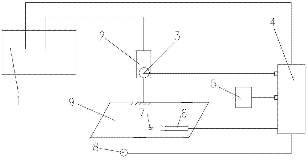
[0026] Such as figure 1 As shown, an electromagnetic positioning system of the present invention includes an electromagnetic locator 4, a magnetic field transmitter 5, an ultrasonic probe 2, an interventional instrument 6, and an ultrasonic imaging system 1, and the ultrasonic imaging system 1 includes a viewing angle selection module and a signal processing module connected in sequence and a three-dimensional display module, the magnetic field transmitter 5 and the ultrasonic imaging system 1 are connected to the electromagnetic locator 4, the ultrasonic probe 2 is connected to the ultrasonic imaging system 1, the ultrasonic probe 2 is equipped with a first positioning senso...


PUM


Abstract

The invention relates to the technical field of medical devices, in particular to an electromagnetic positioning system and a selection method for the three-dimensional image view angle of the electromagnetic positioning system. The system comprises an electromagnetic positioning instrument, a magnetic field transmitter, an ultrasonic probe, an intervening device and an ultrasonic image system. The ultrasonic image system comprises a view angle selection module, a signal processing module and a three-dimensional display module which are connected in sequence. The magnetic field transmitter and the ultrasonic image system are connected with the electromagnetic positioning instrument. The ultrasonic probe is connected with the ultrasonic image system, a first positioning sensor is arranged on the ultrasonic probe, a second positioning sensor is arranged on the intervening device, and the first positioning sensor and the second positioning sensor are connected with the electromagnetic positioning device. When the electromagnetic positioning system is used, a proper view angle selection method is adopted automatically, a diagnosis and treatment part can be displayed in real time, a three-dimensional image of the diagnosis and treatment part can be basically identical with that of a doctor, and the intervening device can be conveniently and accurately guided to conduct diagnosis and treatment of operation and the like. According to the electromagnetic positioning system and the selection method for the three-dimensional image view angle of the electromagnetic positioning system, safety is high, use is convenient and reliable, the medical technology is improved, and the medical risks are lowered.

Description

technical field [0001] The invention relates to the technical field of medical equipment, in particular to an electromagnetic positioning system and a method for selecting a three-dimensional image angle of view. Background technique [0002] At present, the medical electromagnetic positioning system is based on the electromagnetic field theory, combined with computer, signal acquisition and signal processing and other information technologies, can provide three-dimensional positioning in the medical process, guide doctors to implement relevant treatments, and become an important branch of medical instrument research . [0003] With the emergence of various advanced medical imaging equipment such as CT, MRI, and US, the diagnosis and treatment of diseases has achieved three-dimensional digitization, which provides powerful help for doctors to diagnose and treat diseases accurately. However, clinical treatment still depends on the doctor's experience, especially in surgical ...

Claims


Application Information

Patent Timeline
IPC IPC(8): A61B19/00A61B5/06A61B8/00
CPCA61B5/06A61B8/00
Inventor 陈瑞松牟晓勇鹿洪辉杨林
Owner UNITED IMAGING SYST BEIJING CO LTD
Learn More