
A welding method that can increase the connection strength between the gold-sprayed end face of the capacitor and the lead wire

A lead wire connection and welding method technology, which is applied in the field of welding that can increase the connection strength between the gold-sprayed end face of the capacitor and the lead wire, can solve the problems of increased contact resistance, increased loss angle, and reduced service life, so as to achieve reduced contact resistance and no The effect of power reduction and long service life

Active Publication Date: 2016-09-28
ANHUI TONGFENG ELECTRONICS
View PDF6 Cites 0 Cited by
  • Summary
  • Abstract
  • Description
  • Claims
  • Application Information

AI Technical Summary

Problems solved by technology

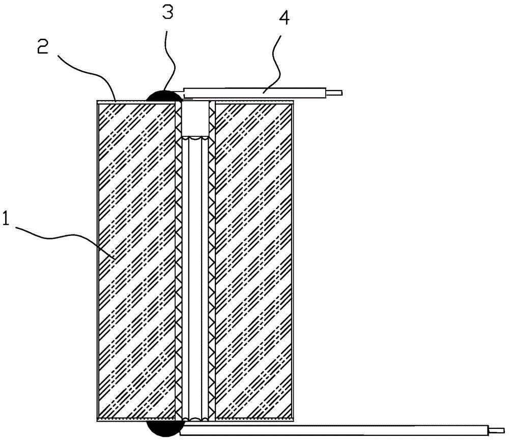
This kind of welding technology has high requirements. The welding material generally uses Φ2mm (or Φ2.5mm) active solder wire with tin content of 60%. The soldering time of the electric soldering iron should not exceed 2 seconds. Solder joint 3, but it may damage the gold-sprayed end face and burn the metallized film, resulting in waste products. If the soldering time is too short, the solder joint is too small, and the tensile force that the solder joint can withstand is small. Pull and fall off, usually the diameter of the solder joint is controlled at 5-8mm, and the height of the solder joint is not higher than 2mm
Because the solder joint is not large, when the lead wire is subjected to tensile force, the attachment surface between the solder and the soldering strip is perpendicular to the direction of the tensile force, and it is easy to produce shear deformation due to the shear force, and it becomes loose until it falls off, so the solder joint bears The tensile force is not high, and the tensile force that the solder joint can withstand is generally not more than 78.4N (8kg). When the capacitor is assembled, the lead wire may still cause loosening of the solder joint due to pulling, which increases the contact resistance and leads to an increase in the loss angle. Capacitors will heat up due to the increase in loss angle during use, causing early failures such as open circuits, thereby reducing service life

Method used


Image

  • A welding method that can increase the connection strength between the gold-sprayed end face of the capacitor and the lead wire
  • A welding method that can increase the connection strength between the gold-sprayed end face of the capacitor and the lead wire
  • A welding method that can increase the connection strength between the gold-sprayed end face of the capacitor and the lead wire

Examples


Embodiment Construction

[0019] The technical solutions in the embodiments of the present invention are clearly and completely described below in conjunction with the accompanying drawings. Apparently, the described embodiments are only some of the embodiments of the present invention, but not all of them. Based on the embodiments of the present invention, all other embodiments obtained by persons of ordinary skill in the art without making creative efforts belong to the protection scope of the present invention.

[0020] The steps of welding method of the present invention are as follows:

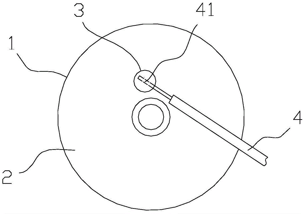
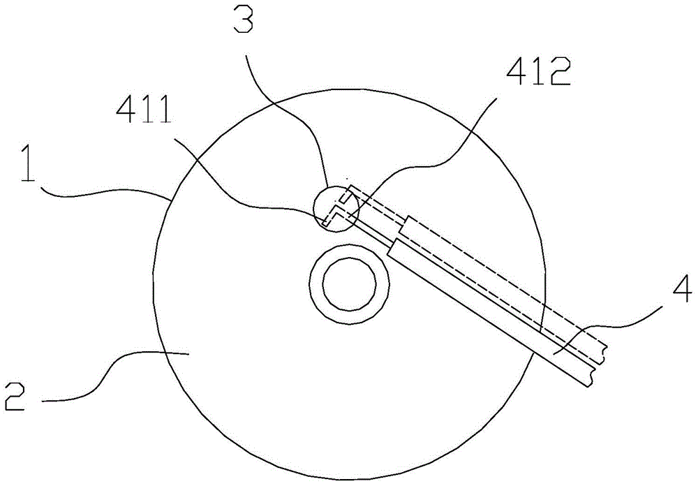
[0021] (1) The welding stripping head 41 at the front end of the lead wire 4 is bent into an angle of 80° to 100° to form the front welding stripping head 411 and the rear welding stripping head 412. Considering the increased stress, the welding stripping head 4 is the best It is best to bend at right angles, considering that the diameter of the solder joint 3 is 5-8 mm, the length of the welding stripping head 4...


PUM

PropertyMeasurementUnit
tensile loadaaaaaaaaaa

Abstract

The invention relates to a welding method capable of increasing the connecting strength of a gold-sprayed end surface of a capacitor and a leading wire. The welding method comprises the steps of bending a welding peeling head of the front end of the leading wire into a front-section welding peeling head and a rear-section welding peeling head; adhering the front-section welding peeling head to the gold-sprayed end surface of a capacitor core assembly, and distributing the rear-section welding peeling head along the leading-out direction of the leading wire; carrying out welding by aligning the front-section welding peeling head; pushing the rear-section welding peeling head into solder before molten solder is solidified; keeping the position of the rear-section welding peeling head until the solder is solidified to form a welding spot. According to the welding method disclosed by the invention, since the front end of the welding peeling head is provided with a bending part, the tension force borne by the welding spot is increased by at least 50%; the leading wire is fully in contact with the solder, a loss angle of the capacitor is reduced, the reactive power is reduced, and the welding method has the advantages of high reliability and long service life.

Description

technical field [0001] The invention relates to a welding method for a gold-sprayed end surface of a capacitor and a lead wire, in particular to a welding method capable of increasing the connection strength between the gold-sprayed end surface of the capacitor and the lead wire. Background technique [0002] Such as figure 1 , 2 As shown, between the upper and lower gold-sprayed end faces 2 of the capacitor core group 1 and the lead wire 4, an electric soldering iron is used to melt the solder wire to weld the welding stripping head 41 of the lead wire with the gold-sprayed end face 2 to form solder joints 3 to achieve connection, thereby Lead out the two electrodes of the capacitor. The end part of the lead wire 4 is stripped off about 5-6mm of the lead wire insulation skin, as a welding stripping head 41 . This kind of welding technology has high requirements. The welding material generally uses Φ2mm (or Φ2.5mm) active solder wire with tin content of 60%. The soldering...

Claims


Application Information

Patent Timeline
Patent Type & Authority Patents(China)
IPC IPC(8): B23K1/00B23K1/20B21F15/00B23K101/36
CPCB21F15/00B23K1/00B23K1/20B23K2101/36Y02P70/10
Inventor 吴平周庆华冯玲
Owner ANHUI TONGFENG ELECTRONICS
Learn More