Transmission brake integrated device for vehicle

A brake device and integrated device technology, applied in the field of vehicles, can solve the problems of vehicle passability, complex structure, large volume, etc., and achieve the effect of narrow research and development requirements, satisfying structural space, and compact structure

Active Publication Date: 2015-07-15
CRRC QISHUYAN INSTITUTE CO LTD
View PDF6 Cites 10 Cited by
  • Summary
  • Abstract
  • Description
  • Claims
  • Application Information

AI Technical Summary

Problems solved by technology

Most of the more advanced new energy vehicles at home and abroad, especially the transmission systems of new energy buses, still adopt low-floor axle solutions, that is, separate motors, brakes, accelerators and decelerators are used on traditional low-floor axles. It is complex, and the axle, motor, brake and reducer respectively occupy the chassis space of the vehicle, and the volume is relatively large, which

Method used


Image

  • Transmission brake integrated device for vehicle
  • Transmission brake integrated device for vehicle
  • Transmission brake integrated device for vehicle

Examples


Embodiment 1

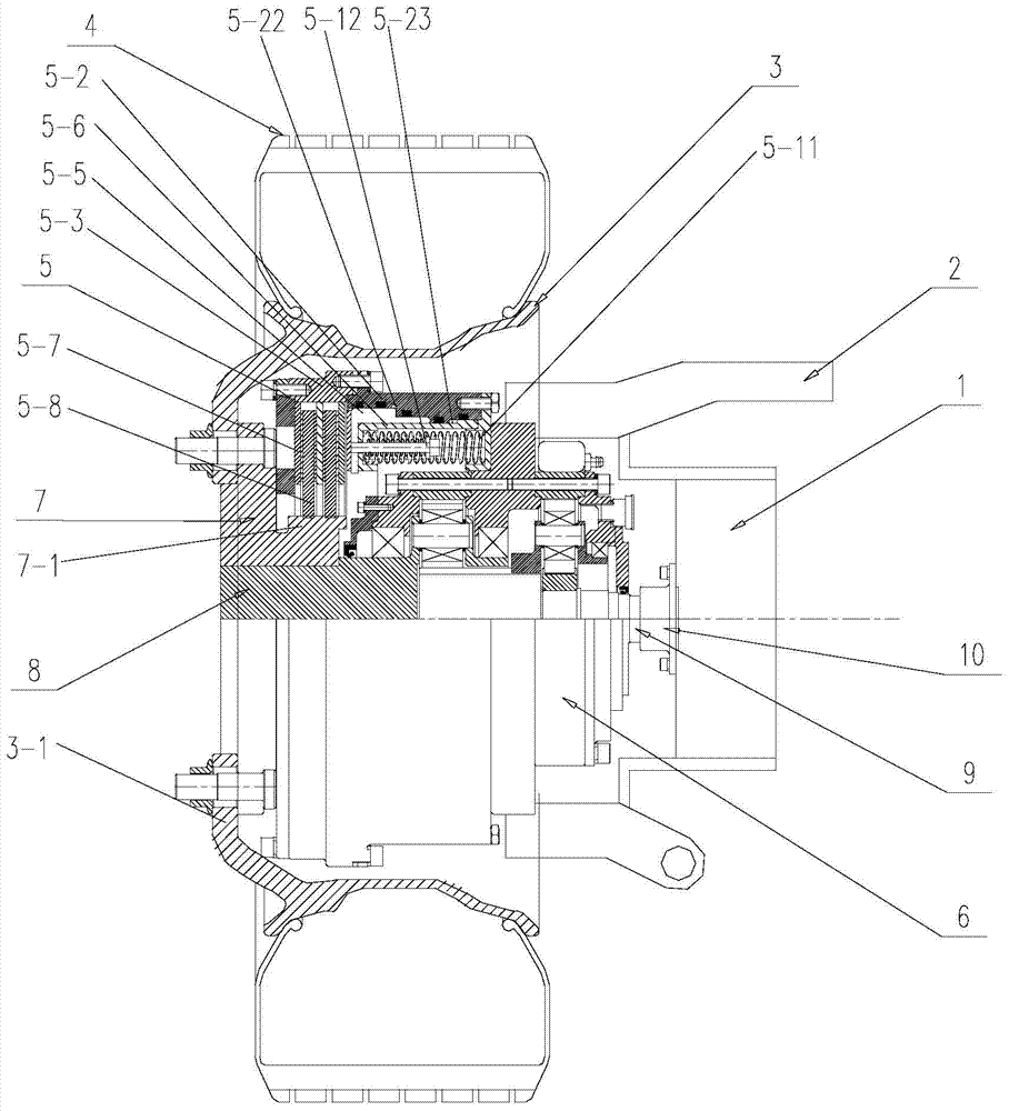
[0017] The basic structure of the vehicle transmission and braking integrated device of this embodiment is as follows: figure 1 As shown, it is mainly composed of a C-section rim 3 located in a vehicle 4 , a brake 5 located in the rim, and a speed reducer 6 .

[0018] One side of the rim 3 has a perforated end plate 3-1 fixedly connected with the output flange 7. The inner side of the output flange 7 radially extends out of the flange flange 7-1.

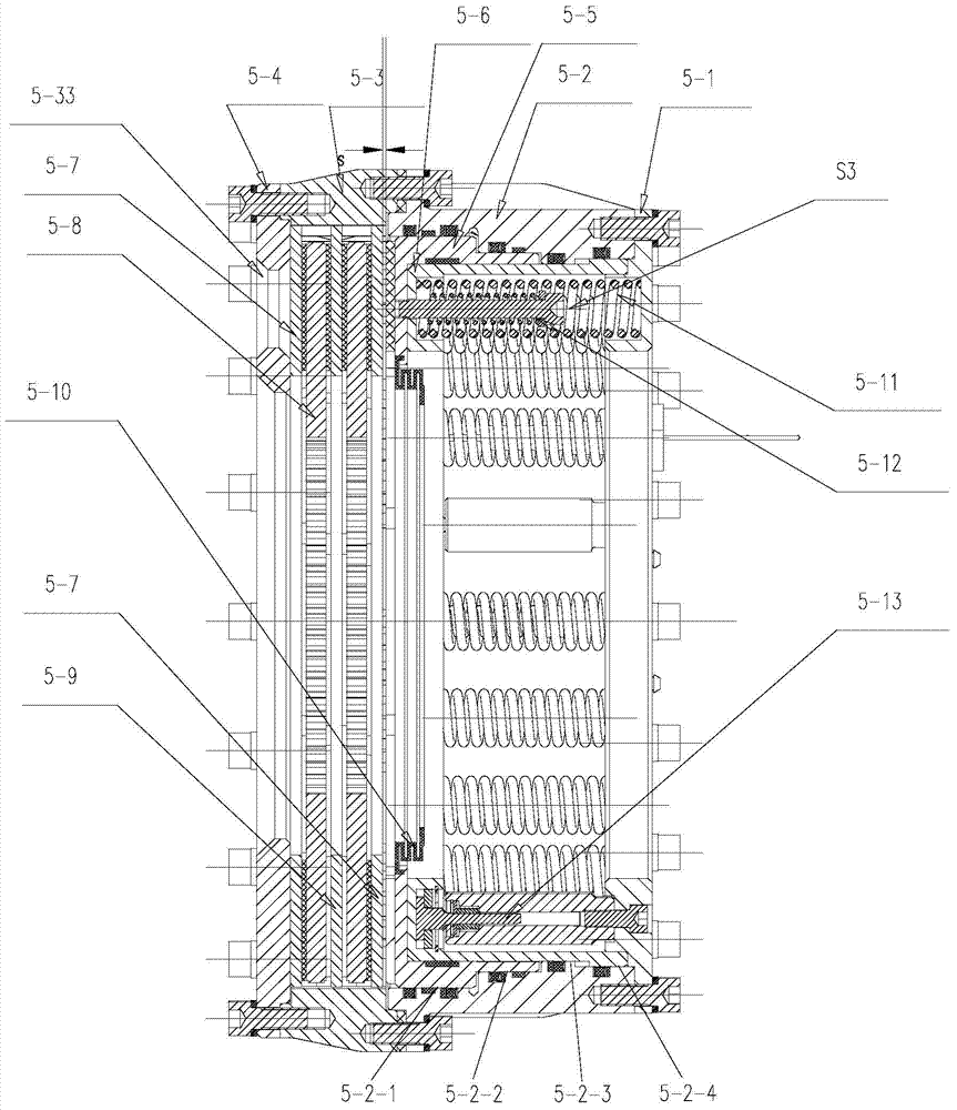
[0019] One end of the brake 5 adjacent to the end plate 3-1 contains a set of outer circles distributed at intervals through the spline structure and the friction plates 5-7 that are circumferentially constrained by the brake housing 5-3 and constitute a moving pair in the axial direction. There is a brake disc 5-8 which is circumferentially constrained by the inner hole through the spline structure and the flange flange 7-1 and constitutes a moving pair in the axial direction. The friction plate and the brake disc constitute a fr...


PUM


Abstract

The invention relates to a transmission brake integrated device for a vehicle, and belongs to the technical field of vehicles. The device comprises a brake positioned in a rim, and a speed reducer, wherein one side of the rim is provided with an open end disk which is fixedly connected with an output flange; friction plates which are distributed at intervals are arranged at one end of the brake close to the end disk; brake discs are arranged between adjacent friction plates; an oil cylinder block is arranged on one side of a friction pair constructed by the friction plates and the brake discs; a travel braking oil cylinder and a parking braking oil cylinder are arranged in the oil cylinder block; a travel piston and a parking piston are arranged in the travel braking oil cylinder and the parking braking oil cylinder respectively; parking springs containing a return mechanism are distributed at intervals along the outer circumference of the parking piston; the speed reducer extends into a cavity in the middle part of the oil cylinder from the open end of the rim; an output shaft on the middle part of the speed reducer is fixedly connected with an output flange; a shell and a brake shell are fixedly connected with a frame. On the premise of ensuring the original functions, the structure can be as compact as possible, and the research and development demands of novel vehicles with narrow structural spaces can be met practically.

Description

technical field [0001] The invention relates to a transmission and braking integrated device, in particular to a vehicle transmission and braking integrated device applied to a new type of automobile, which belongs to the technical field of vehicles. Background technique [0002] With the depletion of oil resources and the improvement of people's awareness of environmental protection, new energy vehicles will become the mainstream of future vehicle development. As far as the applicant knows, in the current development of new energy vehicles, the traditional vehicle transmission system is still used to replace its fuel power unit with a hybrid or pure electric drive unit. Most of the more advanced new energy vehicles at home and abroad, especially the transmission systems of new energy buses, still adopt low-floor axle solutions, that is, separate motors, brakes, accelerators and decelerators are used on traditional low-floor axles. It is complex, and the axle, motor, brake ...

Claims


Application Information

Patent Timeline
IPC IPC(8): B60T1/06B60K17/04
CPCB60K17/04B60T1/065
Inventor 高雷李艳红王村伟陈学伟郑剑云孟永帅宫峰
Owner CRRC QISHUYAN INSTITUTE CO LTD
Why Eureka
Try Eureka