Airplane hydraulic brake system

A braking system and hydraulic technology, applied in the direction of aircraft braking arrangement, control mechanism, vehicle components, etc., can solve problems such as unreasonable layout and potential safety hazards, and achieve the effect of eliminating hidden dangers of accidents, rational structure and lightening burden.

Inactive Publication Date: 2015-07-15
XIAN AVIATION BRAKE TECH
View PDF5 Cites 21 Cited by
  • Summary
  • Abstract
  • Description
  • Claims
  • Application Information

AI Technical Summary

Problems solved by technology

[0004] In order to overcome the shortcomings of unreasonable layout and potential safety hazards in the prior art, the present invention proposes an aircraft hydraulic brake system

Method used


Image

  • Airplane hydraulic brake system
  • Airplane hydraulic brake system

Examples


Embodiment Construction

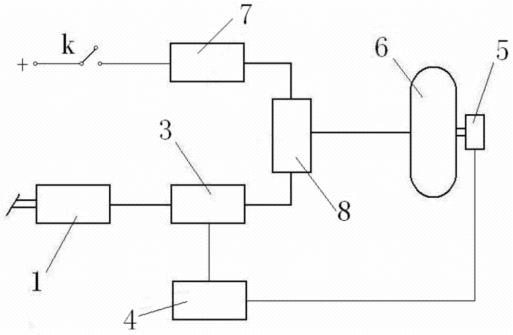
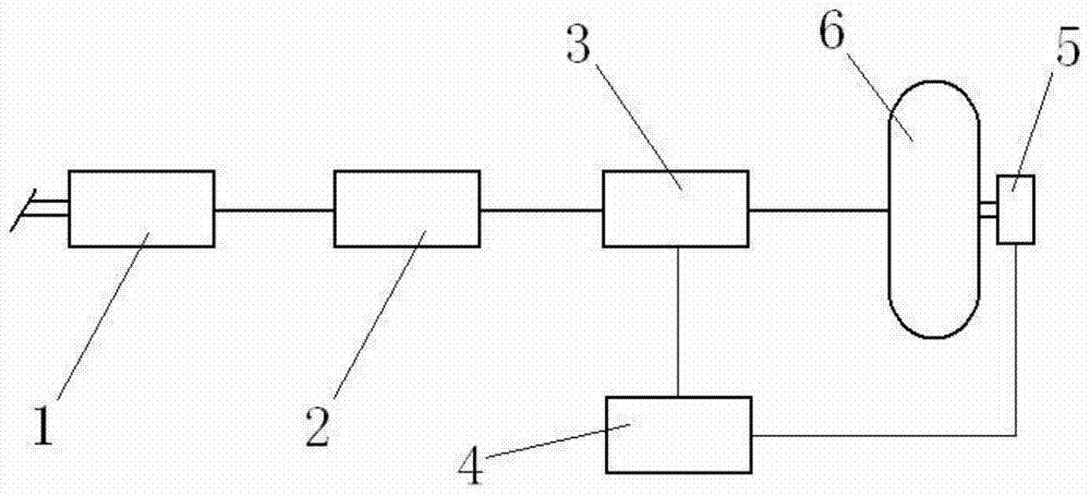
[0022] The front landing gear wheels of modern aircraft generally do not have brakes, and brake devices are equipped on the wheels of the two main landing gears. The two aircraft main landing gears are usually arranged symmetrically on both sides of the aircraft fuselage. This embodiment takes one of the main landing gear and one wheel installed as an example to illustrate the control process of the aircraft hydraulic brake system main landing gear braking the wheel normally and the take-off line braking. Since emergency braking is not involved, the aircraft emergency braking system is not shown in the figure. The emergency braking system is prior art.

[0023] The components of the aircraft hydraulic braking system in this embodiment include: a hydraulic braking valve 1 , a hydraulic control switching valve 2 , an electro-hydraulic servo valve 3 , an anti-skid control box 4 , and a speed sensor 5 .

[0024] The hydraulic brake valve 1 is installed near the pedal mechanism b...


PUM


Abstract

An airplane hydraulic brake system comprises a hydraulic brake valve, a liquid-controlled conversion valve, an electro-hydraulic servo valve, an anti-slide control box and a speed sensor. The liquid-controlled conversion valve is mounted on a downstream hydraulic pipeline of the hydraulic brake valve, the electro-hydraulic servo valve is mounted on a downstream hydraulic pipeline of the liquid-controlled conversion valve, an electrical interface of the electro-hydraulic servo valve is electrically connected with the anti-slide control box through a shielding insulation wire, an oil inlet of the electro-hydraulic servo valve is in pipeline connection with an oil outlet of the liquid-controlled conversion valve, a brake opening of the electro-hydraulic servo valve is in pipeline connection with an oil inlet of a brake device of a brake airplane wheel, and an oil returning opening of the electro-hydraulic servo valve is in pipeline connection with an airplane oil returning pipeline through a hydraulic filler neck and a guide pipe. The airplane hydraulic brake system can meet the ever-growing airplane take-off line brake requirement, is reasonable in structure, easy and convenient to implement, and beneficial for reducing of burdens of a driver, conforms to the man-machine engineering principle and meanwhile the accident potentials caused by false-operation switching on of a take-off line brake switch are eliminated.

Description

technical field [0001] The invention relates to an aircraft wheel hydraulic braking system, in particular to an aircraft hydraulic braking system whose normal braking system of the aircraft fully has the braking capability of the take-off line. Background technique [0002] The aircraft wheel brake system is a component of modern aircraft landing gear, and is the basic guarantee equipment for the safe operation of aircraft take-off, landing roll and ground taxi control. Prevent punctured tires. The modern aircraft wheel braking system usually includes a normal braking system (working medium is hydraulic oil) and an emergency braking system (usually compressed gas). The emergency braking system is a safety measure for the driver to take after the normal braking system fails. Due to the increase of aircraft take-off thrust, the brake pressure required for take-off line brakes is much higher than that required for normal brakes, especially carbon brakes. The existing normal br...

Claims


Application Information

Patent Timeline
Patent Type & Authority Applications(China)
IPC IPC(8): B64C25/44B60T13/74
Inventor 何永乐王红玲赵亚军
Owner XIAN AVIATION BRAKE TECH
Why Eureka
Try Eureka