Sewing machine feeding mechanism

A technology of feeding mechanism and sewing machine, which is applied in the direction of cloth feeding mechanism, sewing machine components, sewing equipment, etc., which can solve the problems of difficult assembly and parts processing, easy loosening of differential tooth brackets, unstable feeding, etc., and achieve reduction in processing Difficult to manufacture, easy to assemble, and the effect of improving production efficiency

Active Publication Date: 2015-07-15
JACK SEWING MASCH CO LTD
View PDF5 Cites 21 Cited by
  • Summary
  • Abstract
  • Description
  • Claims
  • Application Information

AI Technical Summary

Problems solved by technology

The differential rack of this mechanism has only one baffle plate fixed on the main feeding rack to limit its position, so the differential rack is easy to loosen after a period of use, resulting in unstable feeding, noise and other problems, and The structure of this kind of feeding mechanism is relatively complicated, the assembly difficulty and parts processing are relatively difficult, and the production cost is relatively high.

Method used


Image

  • Sewing machine feeding mechanism
  • Sewing machine feeding mechanism
  • Sewing machine feeding mechanism

Examples


Embodiment Construction

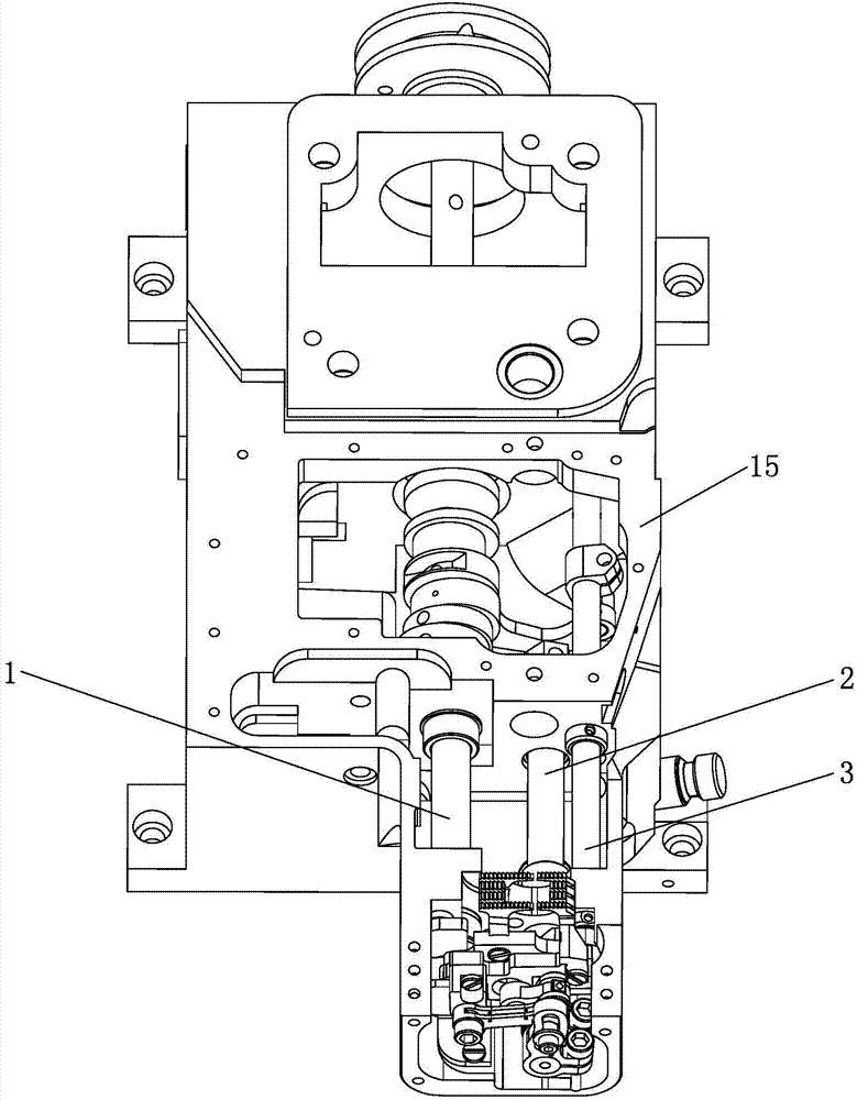
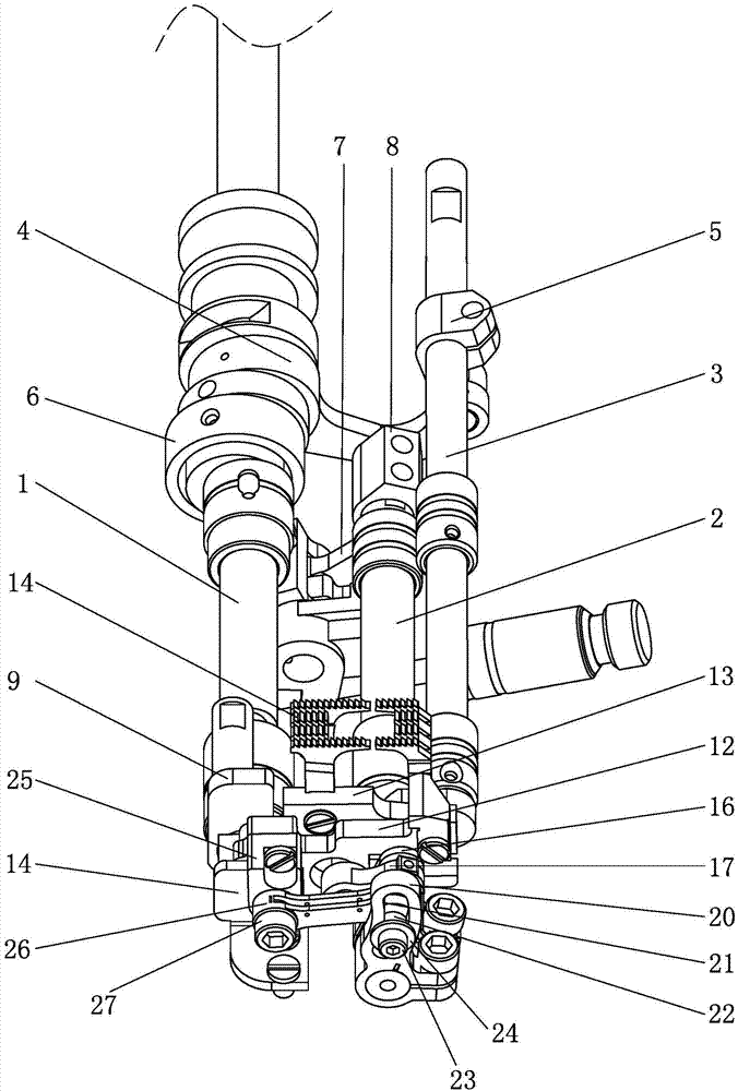
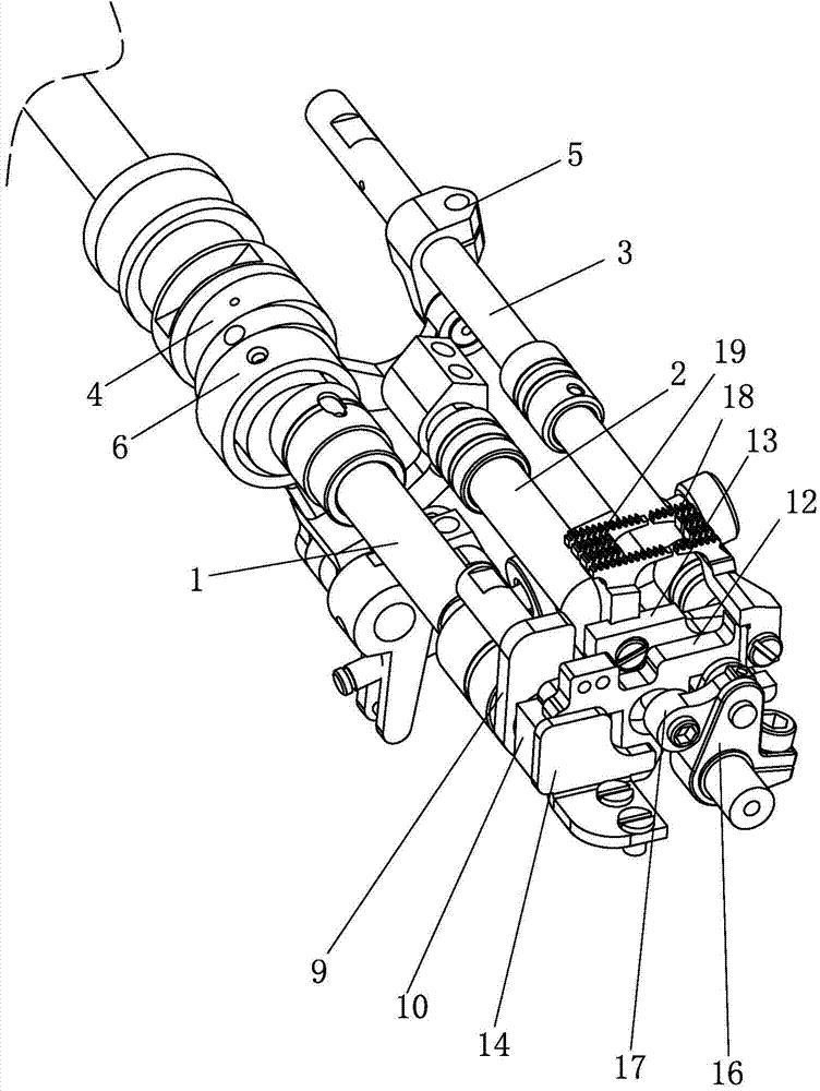
[0020] The present invention will be further described below with specific embodiments in conjunction with the drawings, see figure 1 — Figure 4 :

[0021] A feeding mechanism of a sewing machine includes a lower main shaft 1, a differential shaft 2 and a tooth lifting shaft 3. The lower main shaft 1 is driven to rotate by a motor. One end of the first connecting rod 4 is sleeved and fixed on the lower main shaft 1, and the other end is connected to the first shaft. One end of the crank 5 is hinged, and the other end of the first crank 5 is fixed on the lifting shaft 3 by screws. The rotation of the lower main shaft 1 drives the first connecting rod 4 to reciprocate and drive the lifting shaft 3 to swing. The lower main shaft 1 is also oscillatingly connected with the differential shaft 2 through an eccentric connecting rod 6, a second connecting rod 7 and a second crank 8. The front end of the lower spindle 1 is provided with a lifting crank 9, the lower spindle 1 on the front...


PUM


Abstract

The invention belongs to the technical field of sewing machines and particularly relates to a sewing machine feeding mechanism. A feed lifting crank is arranged at the front end of a lower main shaft. Sliding blocks are fixedly arranged on the lower main shaft. Feed lifting sliding blocks are arranged on the feed lifting shaft. Sliding grooves are formed in the left ends and the right ends of a differential motion tooth frame and a main cloth feeding tooth frame. The sliding blocks and the feed lifting sliding blocks are arranged in the sliding grooves in the two ends of the differential motion tooth frame and the two ends of the main cloth feeding tooth frame. Tooth frame blocking plates are arranged on the front sides of the sliding blocks. The tooth frame blocking plates are in contact connection with the differential motion tooth frame. A first differential motion crank fixed on a differential motion shaft is arranged on the front side of the differential motion tooth frame. The feed lifting crank, the tooth frame blocking plate, the first differential motion crank and the feed lifting shaft press and limit the main cloth feeding tooth frame and the differential motion tooth frame. The first differential motion crank is connected with the main cloth feeding tooth frame through a differential motion connecting rod. Differential motion teeth are arranged on the differential motion tooth frame. Cloth feeding teeth are arranged on the main cloth feeding tooth frame. By two-end clamping limiting, the differential motion tooth frame cannot be loosened even after long-time using.

Description

Technical field [0001] The invention belongs to the technical field of sewing machines, and particularly refers to a sewing machine feeding mechanism. Background technique [0002] The interlock sewing machine is suitable for sewing necklines and cuffs of various elastic fabrics such as knitted underwear, sportswear, T-shirts, bras, and waist skirt elastic bands. Desktop interlock sewing machine is the basic type of interlock sewing machine, which can be used for curling sewing, suitable for curling sewing on the neckline and cuff of underwear and sports shirt. In addition, there are many types of desktop interlock sewing machines, which can be installed with a variety of accessories to realize a variety of functions. They are widely used in all kinds of knitted sewing materials, such as underwear, cotton and wool underwear, sweatshirt pants, T-shirts, men's and women's underwear, and are also suitable for sewing. It can produce various styles of knitted fashion, knitted outerwe...

Claims


Application Information

Patent Timeline
Patent Type & Authority Applications(China)
IPC IPC(8): D05B27/02D05B27/08
CPCD05B27/02D05B27/08
Inventor 刘小刚王志宋兴健
Owner JACK SEWING MASCH CO LTD
Why Eureka
Try Eureka