Gas and coal spontaneous combustion coupling disaster monitoring system and monitoring method in coal mine stope

A monitoring system, coal spontaneous combustion technology, applied in mining equipment, measuring equipment, mining equipment, etc., can solve problems such as inability to guide on-site disaster prevention and control, lack of monitoring means, and inability to display the distribution range of goaf coupling disasters, etc. , to achieve the effect of wide practicability, simple process and easy construction

Active Publication Date: 2016-09-21
SHANDONG UNIV OF SCI & TECH
View PDF6 Cites 0 Cited by
  • Summary
  • Abstract
  • Description
  • Claims
  • Application Information

AI Technical Summary

Problems solved by technology

[0003] Determining the risk area of ​​coupled disasters is the key to the prevention and control of such disasters. However, due to the lack of effective monitoring means to monitor the spatial distribution of coupled disasters, it is not possible to guide the on-site disaster prevention and control work well.
At present, there is no instrument and equipment for directly monitoring the gas and temperature distribution in the goaf space. In the past, the buried pipe observation was carried out in two directions along the trench, and a simple change curve was generated by Excel, which could not display the coupling disaster in the goaf from a three-dimensional perspective. distribution range

Method used


Image

  • Gas and coal spontaneous combustion coupling disaster monitoring system and monitoring method in coal mine stope
  • Gas and coal spontaneous combustion coupling disaster monitoring system and monitoring method in coal mine stope
  • Gas and coal spontaneous combustion coupling disaster monitoring system and monitoring method in coal mine stope

Examples


Embodiment 1

[0055] The present invention will be further described in detail below with an application example of a certain working face in a certain mine.

[0056] The parameters of the working face are the strike length of 100m, the average coal thickness of 6.3m, the mining height of 3m, the average mining and laying ratio of 1:1.1, and the pressure step distance of the working face of 12m. 100m.

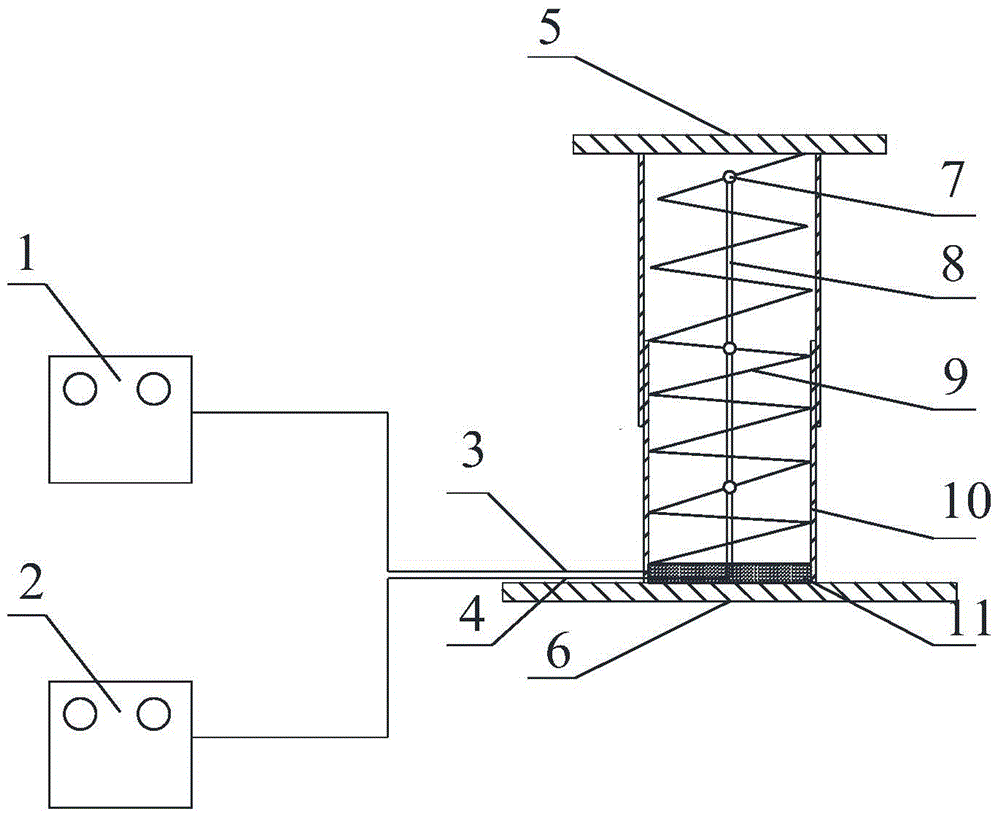
[0057] After calculation, the thickness of the remaining coal in the goaf at the back of the working face is 1.01m, and the thickness of the mixed zone is 0.58m. Therefore, the parameters of the gas sampler can be designed as:

[0058] The length of the upper seamless steel pipe is 800mm, the inner diameter is 150mm, and the wall thickness is 3mm;

[0059] The length of the lower seamless steel pipe is 800mm, the inner diameter is 144mm, and the wall thickness is 3mm;

[0060] The diameter of the lower steel pipe tray is 250mm, the diameter of the upper seamless steel pipe tray is 160mm, a...


PUM

PropertyMeasurementUnit
lengthaaaaaaaaaa
thicknessaaaaaaaaaa
diameteraaaaaaaaaa

Abstract

The invention discloses a system and method for monitoring gas and coal spontaneous combustion coupling disasters on a coal mine stope, and relates to the establishment of a space gas observation and gas and coal spontaneous combustion coupling disaster representation model on a gob of a fully mechanized top-coal workface. The system comprises a stope gas sampler and a monitoring base station. A movable casing is formed by an upper seamless steel tube and a lower seamless steel tube which are connected together in a sleeved mode. The outer side of the upper seamless steel tube and the outer side of the lower seamless steel tube are each provided with a rectangular notch, and the two rectangular notches are placed in the same straight line. Sampling steel tubes are arranged in the rectangular notches, and the sampling steel tubes are of a hollow structure. Three sealed cavities are evenly divided in each sampling steel tube from bottom to top at intervals, and a set of monitoring lines are arranged in each sealed cavity. According to the invention, the stope gas sampler is placed in the gob, and the space three-dimensional distribution of a coupling disaster hazardous area is reestablished and obtained based on real measured data. The system and method have the advantages of being high in pertinency, high in practicability, and capable of being effectively applied to same on-site coupling disaster space characteristic description and directional control.

Description

technical field [0001] The invention belongs to the technical field of coal mine gas and coal spontaneous combustion coupling disaster prevention and control, and in particular relates to a coal mine stope gas and coal spontaneous combustion coupling disaster monitoring system and a monitoring method thereof. Background technique [0002] With my country's high-intensity and intensive exploitation of energy, shallow resources are decreasing day by day, and mines at home and abroad have successively entered the stage of deep resource exploitation. The mechanical characteristics of deep coal and rock mass become more complex, and the amount of coal and rock fragmentation is large, which provides good oxygen and heat storage conditions for coal spontaneous combustion. The existence and movement of high gas content zones and gas accumulation zones are important factors for gas explosions and combustion accidents in mines, and coal spontaneous combustion provides fire source cond...

Claims


Application Information

Patent Timeline
Patent Type & Authority Patents(China)
IPC IPC(8): E21F17/00G01D21/02G01N1/22
CPCE21F17/00G01D21/02G01N1/22G06F30/00
Inventor 张孝强王刚程卫民孙路路杜文州颜国强黄启铭杨鑫祥武猛猛
Owner SHANDONG UNIV OF SCI & TECH
Why Eureka
Try Eureka