
Display device and light source correction method for display device

A light source correction and light source technology, applied in the field of light source correction, can solve problems such as deviation when correction is not taken into account, interpretation error, and the tendency of brightness of display units to dim, and achieve the effect of solving brightness reduction and color deviation.

Active Publication Date: 2015-07-15
QISDA SUZHOU +1
View PDF4 Cites 2 Cited by
  • Summary
  • Abstract
  • Description
  • Claims
  • Application Information

AI Technical Summary

Problems solved by technology

[0003] Generally, liquid crystal displays use light-emitting diodes as light sources. As the use time increases, the luminous efficacy of the light source will naturally decay, resulting in a tendency for the brightness of the display unit to become darker than when it leaves the factory; After use, due to the attenuation of light-emitting diode materials, polymer liquid crystal materials, light sources, color filters, driver ICs, and electrical and optical characteristics of the internal components of the panel, the brightness of the screen will decrease or the color will deviate. It even deviates from the standard requirements and affects the quality of the display unit, causing interpretation errors; in addition, when the LCD is turned on, the LED backlight module fails to perform electro-optical conversion in time, so that the brightness and color temperature cannot reflect the required brightness and color in time, and it takes a while In order for the light source to achieve a stable light output, it is necessary to provide efficient and accurate compensation adjustments to keep the display device at the backlight brightness and color temperature when it leaves the factory. It is in a stable state to ensure that the display maintains the color temperature and brightness consistency after the display is cold or warmed up or used for a period of time
[0004] Due to the natural attenuation of the display unit, users can only consider sending it to the factory for calibration or relying on manual adjustment and visual judgment to perform calibration between displays, and it is difficult to achieve the quality of calibration; therefore, some users purchase related optics The detection equipment (such as a colorimeter) performs calibration by itself, and the method is to obtain the color value of the image in the display unit, and then compare it with the color value measured by the standard colorimeter to correct the picture parameters; however At present, this kind of special testing equipment is still expensive, and it is impossible to directly convert the picture parameters of several monitors to correspond automatically; moreover, the attenuation speed of the general colorimeter is even faster than that of the display unit, often causing the user to first adjust the colorimetric After the meter is sent back to the original factory for calibration, the brightness and chromaticity of the display unit can be adjusted, which is quite inconvenient to use
[0005] In conventional technologies such as patent US7696964, LED backlight modules are compensated for brightness or color temperature. However, conventional technologies only compensate for a single brightness or color temperature without consideration of integration. The measured values ​​of red, blue, and green are directly used for calibration, without considering the error of the measurement value due to the existence of infrared light, which leads to the influence of the deviation during calibration

Method used


Image

  • Display device and light source correction method for display device
  • Display device and light source correction method for display device
  • Display device and light source correction method for display device

Examples


Embodiment Construction

[0025] In order to have a further understanding of the purpose, structure, features, and functions of the present invention, the following detailed descriptions are provided in conjunction with the embodiments.

[0026] Please refer to figure 1The structure schematic diagram of the display device 10 of the present invention, the structure of the display device 10 includes: a liquid crystal module 130 , a back cover 140 , a light source 110 and a sensing module 120 . The light source 110 can be an LED light source module with three primary colors of red, blue, and green. When adjusting the light source, the power supply of the light source with three primary colors of red, blue, and green can be adjusted. In addition, the light source 110 can also use an LED light source module packaged by red and blue LED chips and green phosphor powder. When adjusting the light source, only the red and blue light sources can be adjusted for power supply. In the present invention, as long as ...


PUM


Abstract

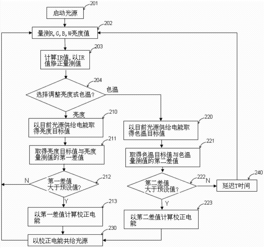
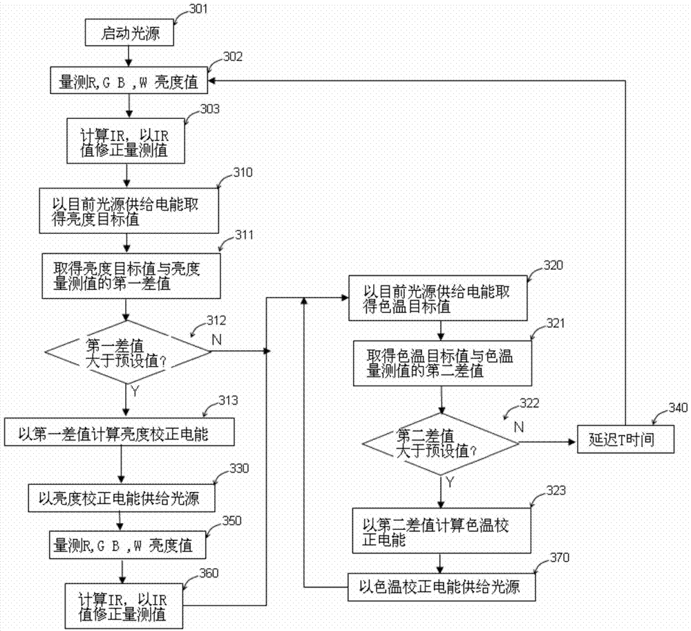
The invention provides a display device and a light source correction method for the display device. The display device comprises a liquid crystal module, a back cover, light sources and a sensing module; the sensing module is used for measuring red light values, blue light values, green light values and white light values of the light sources; the light sources and the sensing module are arranged between the liquid crystal module and the back cover; the light source correction method comprises the following steps of starting the light sources, and measuring a first red light value, a first blue light value, a first green light value and the white light value of the light sources; calculating an infrared light value according to the first red light value, the first blue light value, the first green light value and the white light value, and subtracting the infrared light value from one of the first red light value, the first blue light value and the first green light value for correcting the supplied electric energy of the light sources. According to the display device and the light source correction method for the display device, provided by the invention, in consideration of the influences of infrared rays on measured values, the problems of bright reduction and color bias of the display device in the prior art are solved.

Description

technical field [0001] The invention relates to a display device and a light source correction method of the display device, in particular to a display device and a method for correcting brightness and color temperature of a backlight source of the display device. Background technique [0002] Display technology has developed rapidly in recent years, and expert-level displays that require precise color and brightness are gradually being used in professional fields such as art advertisement design, professional drawing displays, printing and publishing companies, and medical diagnosis that require high color quality of display units. , when working, the several monitors used must have the same screen display (such as brightness and color temperature, etc.) as possible to achieve the required image quality. These professional-level LCD monitors currently use LED light sources as The light source of the backlight module, the LED light source can be an LED light source with thre...

Claims


Application Information

Patent Timeline
IPC IPC(8): F21S8/00F21V19/00F21V9/10F21V9/40
CPCG02F1/133609G09G3/3413
Inventor 庄舒萍
Owner QISDA SUZHOU
Learn More