
Large-size measuring experimental apparatus and method for air flow in cabin based on PIV

An air flow and experimental device technology, which is applied in the field of experimental research of cabin environmental parameters, can solve the problems of inability to meet the analysis and optimization design of air flow in the cabin, inability to obtain complete flow information in large-sized cabins, and small size. To achieve the effect of convenient and flexible selection of measurement sections, complete and rich flow field information, and comprehensive range

Inactive Publication Date: 2015-07-15
TIANJIN UNIV
View PDF9 Cites 36 Cited by
  • Summary
  • Abstract
  • Description
  • Claims
  • Application Information

AI Technical Summary

Problems solved by technology

However, there are still many limitations and deficiencies in the application of PIV technology in the cabin environment
Among them, the main disadvantage is that the size of the PIV measurement area is limited by the light intensity. Compared with the size of the entire cabin, it is relatively small, and it cannot obtain complete flow information in the large-sized cabin, and cannot satisfy the analysis and optimization of the air flow law in the cabin. design requirements
Existing research still lacks the experimental device construction and system parameter setting method for large-scale PIV measurement in the cabin environment

Method used


Image

  • Large-size measuring experimental apparatus and method for air flow in cabin based on PIV
  • Large-size measuring experimental apparatus and method for air flow in cabin based on PIV

Examples


Embodiment Construction

[0019] The technical solutions of the present invention will be described in further detail below in conjunction with the accompanying drawings and specific embodiments, and the described specific embodiments are only to illustrate the present invention, and are not intended to limit the present invention.

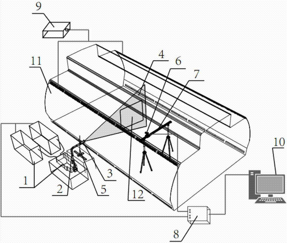
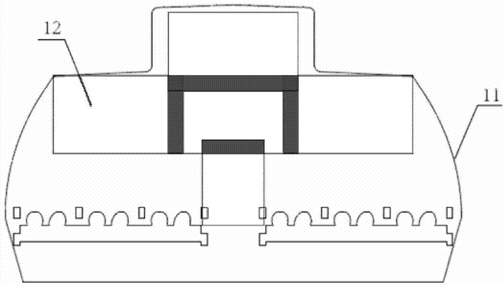
[0020] Such as figure 1 and figure 2 As shown, the present invention proposes a large-scale measurement experimental device for air flow in a cabin based on PIV, including a high-power double-pulse laser system, a particle image capture system, a synchronous controller 8, a tracer particle smoke generator 9 and a computer 10 .

[0021] The high-power double-pulse laser system is placed outside the measured nacelle model 11 (the side of the transparent part in the figure), and the high-power double-pulse laser system is the light source part of the entire measurement system. The high-power double-pulse laser system includes a high-power double-pulse laser 1, a light guid...


PUM

PropertyMeasurementUnit
Thicknessaaaaaaaaaa

Abstract

The invention discloses a large-size measuring experimental apparatus for air flow in a cabin based on PIV. The apparatus comprises a large-power dipulse laser system, a particle image shooting system, a synchronizing controller, a tracer particle fog generator and a computer. In the process of measurement, a light sheet lens assembly is used to adjust the waist of a laser light sheet to allow the waist to be located in a measurement subregion; and a camera guide rail is used to control the measurement position of a high-resolution CCD camera. Tracer particle fog is released into a measurement cabin model; the synchronising controller is used to regulate and control the large-power dipulse laser system and the high-resolution CCD camera so as to obtain a double-frame tracer particle image at every moment; computer analysis software is used for self-adaption cross-correlation processing of the image so as to obtain information about an instantaneous flow field at every moment; time averaging is carried out on the instantaneous flow field at every moment so as to obtain a time-averaged flow field; and the time-averaged flow fields in all the measurement subregions are spliced together so as to obtain integral high-resolution time-averaged flow field data of a large-size cross section in the cabin, and the data is used for flow field characteristic analysis and verification of numerical calculation results.

Description

technical field [0001] The invention relates to the field of experimental research on environmental parameters of a cabin, in particular to a large-scale optical experimental device and a measurement method for complex air flow in the cabin. Background technique [0002] With the development of science and technology and civil aviation, civil passenger aircraft, as a means of transportation that provides high-speed and fast public transportation services, has gradually become a popular way of travel. At present, more than 2 billion people around the world choose to travel by air every year, and this number will continue to increase. As the number of air passengers continues to increase, so will the problems posed by flying. Many passengers feel more or less uncomfortable when taking an airplane. At the same time, international flights greatly increase the chances of rapid international spread of infectious diseases. Therefore, how to create a safe, healthy and comfortable...

Claims


Application Information

Patent Timeline
IPC IPC(8): G01N21/85G01N21/01
Inventor 刘俊杰曹晓东李佳钰
Owner TIANJIN UNIV
Learn More