Supercharge Your Innovation With Domain-Expert AI Agents!

Field depth recognition optical device and imaging method for virtual reality 3D scene

A virtual reality and optical device technology, applied in the field of optical imaging, can solve the problems of not being light enough, not having the function of depth of field recognition, and not being able to be miniaturized, and achieving the effects of simple structure, low production cost, and easy use.

Active Publication Date: 2017-09-22
JINAN UNIVERSITY
View PDF4 Cites 0 Cited by
  • Summary
  • Abstract
  • Description
  • Claims
  • Application Information

AI Technical Summary

Problems solved by technology

However, at present, the display of 3D stereoscopic images generally requires large-scale 3D stereoscopic movie projection systems (such as movie theaters or home theaters, etc.), which cannot be miniaturized and are not light enough, so it is difficult to realize simple and light portable devices such as household handheld or wearable devices. Way
[0003] In addition, according to current reports, some large Netcom companies are planning to launch some wearable virtual reality 3D glasses for displaying games or videos in the next few years, but according to their reports, the structure only uses one display screen, and in actual use , these structures do not have the function of depth recognition, so their three-dimensional effect is not satisfactory

Method used


Image

  • Field depth recognition optical device and imaging method for virtual reality 3D scene
  • Field depth recognition optical device and imaging method for virtual reality 3D scene

Examples


Embodiment 1

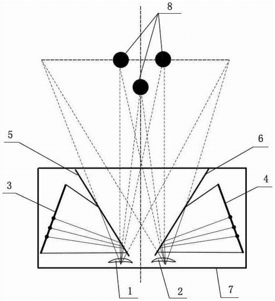
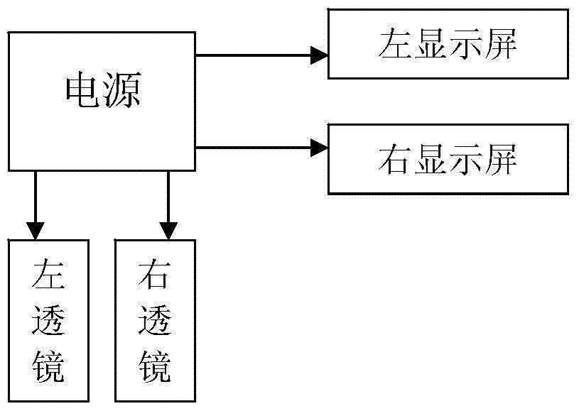
[0026] In this embodiment, a depth-of-field recognition optical device for a virtual reality 3D scene, such as figure 1 As shown, it includes a power supply (not shown in the figure), a variable focus lens group, two reflectors and two display screens. The variable focus lens group is arranged in front of the human eye, and the two reflectors are symmetrically arranged in front of the variable focus lens group. , and the two mirrors are symmetrically placed at an angle of 50-70°, and the two display screens are correspondingly arranged on the outside of the two mirrors; the power supply is respectively connected with the zoom lens group and the two display screens. Wherein, the size and size of each display screen are the same as each reflector.

[0027] The optical structure also includes a housing 7, in which a power supply, a variable focus lens group, two mirrors and two display screens are all arranged. The shell is a black shell inside, which can shield and prevent the ...

Embodiment 2

[0038] This embodiment is a depth of field recognition optical device for a virtual reality 3D scene. Compared with Embodiment 1, the difference is that both the left display screen and the right display screen are 5-inch high-definition digital display screens, and the resolution is more than or equal to 1920 ×1080, the size of the display makes the viewing angle available to both eyes about 120°.


PUM


Abstract

The invention discloses a field depth identification optical device for a 3D (three-dimensional) virtual reality scene and an imaging method of the field depth identification optical device. The device comprises a power supply, a variable focus lens set, two reflective mirrors and two display screens, wherein the variable focus lens set is arranged in front of human eyes; the reflective mirrors are symmetrically arranged in front of the variable focus lens set; an included angle of 50-70 degrees is formed between the reflective mirrors; the display screens are correspondingly arranged on the outer sides of the reflective mirrors; the power supply is connected with the variable focus lens set and the display screens. The imaging method comprises the following steps: mirror images having parallax are played by the display screens at the same time, reflected through the reflective mirrors and refracted through the lens set and then enter the human eyes, and a 3D image different in distance is generated in human brain by amplifying the parallax of the images of the display screens, so that the 3D virtual reality scene is generated in the human eyes. The field depth identification optical device adopts an ingenious optical design, so that the whole device is simple in structure, small and portable, can be mounted on the head, and can be better popularized in the fields of domestic entertainment and healthy diagnosis and treatment.

Description

technical field [0001] The invention relates to the technical field of optical imaging, in particular to a depth-of-field recognition optical device and an imaging method thereof for a virtual reality 3D scene. Background technique [0002] Virtual reality 3D scene display includes 3D entertainment games and film and television program appreciation, which is a hot spot in the current technology field. However, at present, the display of 3D stereoscopic images generally requires large-scale 3D stereoscopic movie projection systems (such as movie theaters or home theaters, etc.), which cannot be miniaturized and are not light enough, so it is difficult to realize simple and light portable devices such as household handheld or wearable devices. Way. [0003] In addition, according to current reports, some large Netcom companies are planning to launch some wearable virtual reality 3D glasses for displaying games or videos in the next few years, but according to their reports, t...

Claims


Application Information

Patent Timeline
Patent Type & Authority Patents(China)
IPC IPC(8): G02B27/22G02B27/01
CPCG02B30/27G02B30/35
Inventor 黄耀熊
Owner JINAN UNIVERSITY
Features
  • R&D
  • Intellectual Property
  • Life Sciences
  • Materials
  • Tech Scout
  • Unparalleled Data Quality
  • Higher Quality Content
  • 60% Fewer Hallucinations
Learn More