H2 filtration-based signal delay elimination method for rhodium self-powered detector

A technology of self-supplied energy detector and signal delay, which is applied in the direction of radiation measurement, neutron radiation measurement, instruments, etc., and can solve problems that are difficult to apply

Inactive Publication Date: 2015-07-15
NUCLEAR POWER INSTITUTE OF CHINA
View PDF5 Cites 0 Cited by
  • Summary
  • Abstract
  • Description
  • Claims
  • Application Information

AI Technical Summary

Problems solved by technology

[0004] At present, the elimination of signal delay applied to rhodium self-powered detectors is mainly based on the Kalman filter. When it is applied, it must be assumed that the external disturbance input signal of the system is a white noise signal with known statistical properties. When the statistical properties of the input signal are difficult to obtain This method is difficult to apply when

Method used


Image

  • H2 filtration-based signal delay elimination method for rhodium self-powered detector
  • H2 filtration-based signal delay elimination method for rhodium self-powered detector
  • H2 filtration-based signal delay elimination method for rhodium self-powered detector

Examples


Embodiment

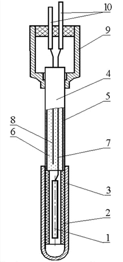
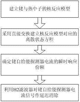
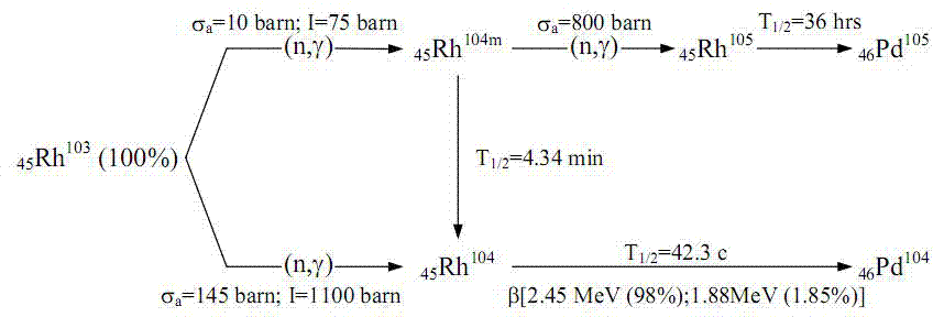
[0075] Such as figure 1 The structure diagram of rhodium self-sufficient neutron detector shown, in which the names of the parts of each serial number correspond to: 1-emitter, 2-insulation layer, 3-collector, 4-wire, 5-protective shell, 6-insulation Cable, 7-current line, 8-base line, 9-sealed tube, 10-current output terminal. The rhodium self-supplied energy neutron detector, its characteristic parameter is: λ 1 =ln2 / 42.3s -1 =0.016386s -1 ,λ 2 =ln2 / 4.34 / 60s -1 =0.00266186s -1 , c=0.06, a 1 =0.879,a 2 = 0.061. image 3 It is the principle process diagram of rhodium and neutron nuclear reaction, for image 3 During the reaction process, the figure 1 device for measurement. Such as figure 2 As shown, the method for eliminating the signal delay of rhodium self-powered detectors based on H2 filtering includes the following steps carried out in sequence: step 1, establishing the nuclear reaction model of rhodium and thermal neutrons; step 2, adopting direct transform...

Embodiment 2

[0116] This embodiment makes the following further limitations on the basis of Embodiment 1: In the case of shifting, this embodiment also includes processing the original signal according to the following signal processing method: in the shifting area, assuming The sub-flux remains unchanged, and then the current signal generated by the neutron flux density is reversed, and then subtracted from the actual output current of the detector to obtain the shifting mutation component; outside the shifting area, the detector output current minus the shifting The mutation component is obtained to obtain the current signal generated by the neutron flux density, and then the delay elimination process is performed on this current signal.

[0117] The shift area design structure of this embodiment is as follows:

[0118] In the shift area (k 1 ≤k≤k 2 ), assuming that the neutron flux density remains constant, then:

[0119] n(k+1)=n(k) (13)

[0120] J ...


PUM


Abstract

The invention discloses an H2 filtration-based signal delay elimination method for a rhodium self-powered detector. The H2 filtration-based signal delay elimination method comprises the following steps which are performed sequentially: step 1) establishing a nuclear reaction model of rhodium and thermal neutrons; step 2) establishing a discrete state equation corresponding to the nuclear reaction model by adopting direct transformation; step 3) determining the share of transient response of the rhodium self-powered detector; and step 4) performing delay elimination on current signals of the rhodium self-powered detector by using an H2 filter. When the H2 filtration-based signal delay elimination method disclosed by the invention is applied, delay elimination treatment can be performed on the current signals of the rhodium self-powered neutron detector, noise can be effectively inhibited, the rhodium self-powered neutron detector can be used normally in transient working condition of a reactor, and by using the method, statistical properties of external disturbance input signals do not need to be known in advance.

Description

technical field [0001] The invention relates to a signal processing technology of a rhodium self-powered neutron detector used in an advanced core measurement system (on-line monitoring system for nuclear reactor power distribution), in particular to a method for eliminating the signal delay of the rhodium self-powered detector based on H2 filtering. Background technique [0002] The rhodium self-supplied neutron detector used as the in-core detector of the advanced core measurement system, the secondary nuclide produced by the reaction of the sensitive material rhodium and the neutron undergoes beta decay to generate a current, and the magnitude and location of the current in a steady state The flux is directly proportional, so by measuring the rhodium self-powered detector can infer the neutron flux at its location. Since the main component of this type of detector current is produced by the β decay of secondary nuclides, in the transient state of the reactor (the neutron ...

Claims


Application Information

Patent Timeline
Patent Type & Authority Applications(China)
IPC IPC(8): G21C17/108G01T3/00G06F19/00
CPCG01T3/00G16Z99/00G21C17/108Y02E30/30
Inventor 龚禾林陈长彭星杰赵文博刘启伟李向阳李庆于颖锐
Owner NUCLEAR POWER INSTITUTE OF CHINA
Why Eureka
Try Eureka