Bend type shielded mcu bus plug

A bus plug and curved technology, applied in the field of curved shielded MCU bus plugs, can solve the problems of not meeting the use requirements of new energy vehicles on curved shielded plugs, poor shielding effectiveness of shielding processing methods, and inability to meet the use requirements, etc. Achieve the effect of benefiting cost control and mass production, benefiting cost control and low production cost

Active Publication Date: 2017-06-06
SICHUAN YONGGUI SCI & TECH CO LTD
View PDF13 Cites 0 Cited by
  • Summary
  • Abstract
  • Description
  • Claims
  • Application Information

AI Technical Summary

Problems solved by technology

[0003] The traditional curved outlet electrical connector plug generally adds an elbow at the end of the plug to achieve the purpose of the curved outlet. The elbow and the plug shell are connected by threads or buckles. , only suitable for small current plugs, because high current plugs need to use cables with larger cross-sectional areas, and cables with large cross-sectional areas have a larger turning radius, and the solution of adding a bend at the end of the plug cannot meet the requirements; the traditional For a plug with a large current curved outlet, generally a terminal and a wire connector are used first, and then the terminal is connected to the contact to achieve a curved outlet. Type outlet, but after the shell is made into a component, the protection level is difficult to meet the standard; the traditional angled connector plug with shielding function usually uses a pair of separate contacts to realize the conduction between the shields. This method of shielding treatment The shielding effect of the method is not good, and because of the extra shielded conductive contact pairs, the size of the connector is increased. It can be seen that the traditional bent outlet plug with shielding function cannot meet the requirements of modern industrial electrical systems, especially Requirements for the use of curved shielded plugs for new energy vehicles

Method used


Image

  • Bend type shielded mcu bus plug
  • Bend type shielded mcu bus plug
  • Bend type shielded mcu bus plug

Examples


Embodiment

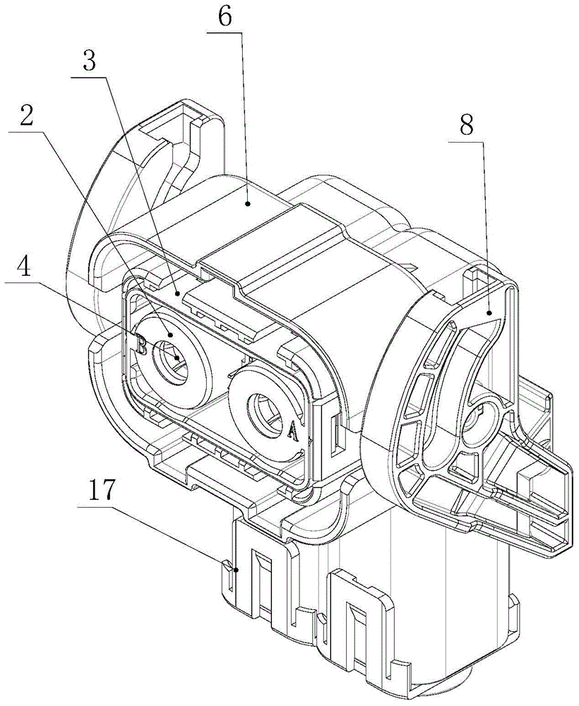
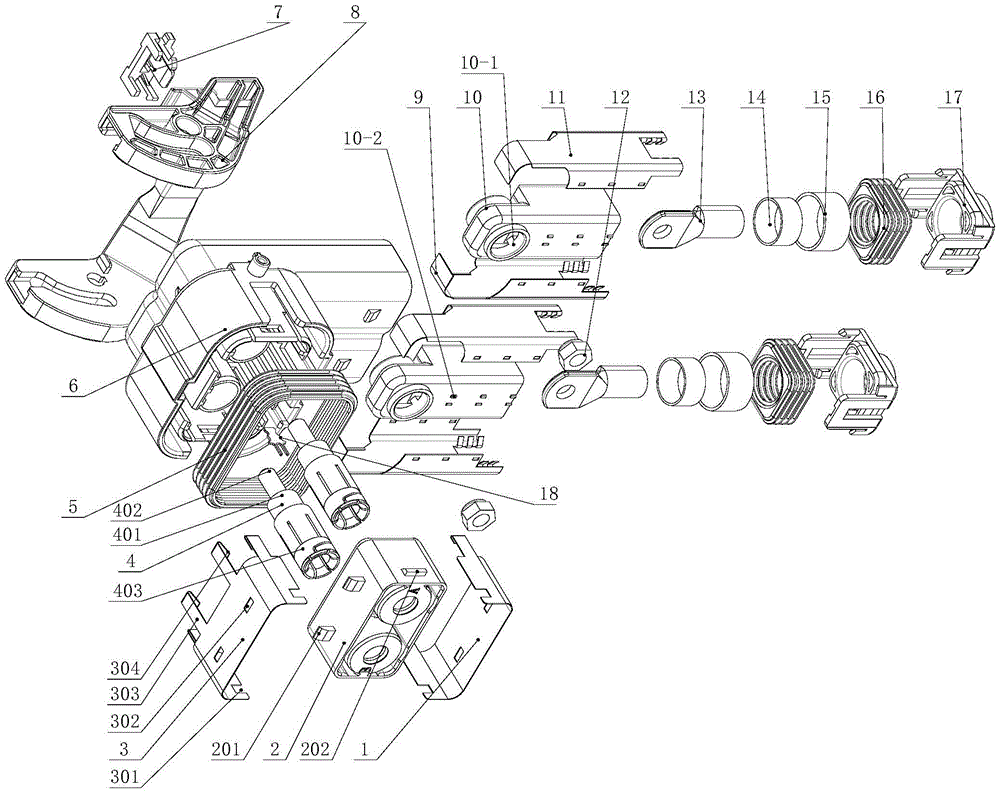
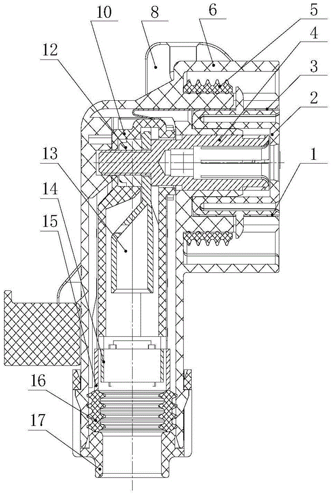
[0045] like Figure 1-3 As shown, a curved shielded MCU bus plug consists of a lower shield 1, a jack mounting plate 2, an upper shield 3, a jack assembly 4, a sealing ring 5, a plug shell 6, a lock block 7, a handle 8, The left shield 9, the sheath 10, the right shield 11, the self-locking nut 12, the connection terminal 13, the shield pad cover 14, the shield pressure sleeve 15, the sealing wire body 16, and the tail cap 17 are formed.

[0046] like Figure 4 and Figure 5 As shown, the plug housing 6 is generally "L"-shaped, and is divided into an insertion part 601 and a wiring part 602. The periphery of the insertion part 601 is provided with a plurality of fool-proof keyways 603, and the two sides of the insertion part 601 There are two hollow rotating shafts 608 arranged symmetrically at the root. On the inner ring of the mating part 601, there is a sealing ring installation platform 605. The upper and lower sides of the installation platform 605 are equipped with mount...


PUM


Abstract

The invention discloses a bending type shielded MCU (Micro Control Unit) bus plug and relates to the field of electrical connectors in the field of new energy vehicles, industrial equipment and urban rails and railway vehicle electrical appliances. The bending type shielded MCU bus plug consists of a lower shielding cover, a jack mounting plate, an upper shielding cover, a jack component, a sealing ring, a plug housing, a locking block, a handle, a left shielding cover, a protective sleeve, a right shielding cover, a self-locking nut, a connecting terminal, a shielding cushion cover, a shielding pressure sleeve, a wire sealing body and a tail cover. With the adoption of threaded switchover, bending type wire outgoing is realized; in an assembly state, the two ends of the jack component are respectively fixed in a jack mounting hole and a jack positioning hole of the plug shell; the connecting terminal is rigidly connected with the jack component through connecting threads, so that when a cable is subjected to axial stress, the jack component cannot incline at an inserting position. The bending type shielded MCU bus plug has the advantages of being small in size, good in shielding effectiveness, low in production cost, high in production efficiency, easy to operate, reliable in contact part contact and the like.

Description

technical field [0001] The invention relates to electrical connectors in the electrical fields of new energy vehicles, industrial equipment, urban rail and railway vehicles, in particular to curved shielded MCU bus plugs used in new energy vehicles. Background technique [0002] In modern industrial electrical systems, the use of electrical connectors is becoming wider and wider, and the number is increasing. There are also more and more requirements for the outlet methods of the connectors, and the demand for 90-degree bent outlets is the majority. [0003] The traditional curved outlet electrical connector plug generally adds an elbow at the end of the plug to achieve the purpose of the curved outlet. The elbow and the plug shell are connected by threads or buckles. , only suitable for small current plugs, because high current plugs need to use cables with larger cross-sectional areas, and cables with large cross-sectional areas have a larger turning radius, and the soluti...

Claims


Application Information

Patent Timeline
Patent Type & Authority Patents(China)
IPC IPC(8): H01R13/648H01R13/02H01R13/46H01R13/64H01R13/62
CPCH01R13/02H01R13/025H01R13/46H01R13/62H01R13/64H01R13/648
Inventor 李统刚彭果
Owner SICHUAN YONGGUI SCI & TECH CO LTD
Why Eureka
Try Eureka