LTCC-LTCF composite circuit substrate structure
A LTCC-LTCF, circuit substrate technology, applied in the direction of circuit substrate materials, printed circuit components, etc., can solve the problem that a single LTCC cannot achieve integrated miniaturization of a single LTCF in the integrated design of microwave circuits, and achieve the effect of strong practical value.
- Summary
- Abstract
- Description
- Claims
- Application Information
AI Technical Summary
Problems solved by technology
Method used
Image
Examples
Embodiment 1
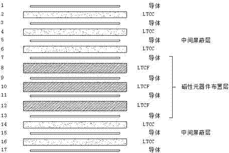
[0029] Example 1: figure 1 It is a "3C + 3F + 2C" composite laminated circuit substrate structure. Among them, the conductors with serial numbers 7 to 13 and the LTCF layer constitute the "magnetic component layout layer", and the integrated design of magnetic components such as inductors and transformers is carried out in this area (LTCF layer is used as the magnetic core, and the conductors printed on the LTCF layer Graphics constitute inductors or transformer coils); two layers of conductors with serial numbers 5 and 15 respectively form an "intermediate shielding layer" to isolate magnetic components from other circuits; the remaining LTCC layers and conductor layers are used for integrated design of capacitors and RF components and other circuit lines; the circuit patterns of each layer are connected through metal vias.
Embodiment 2
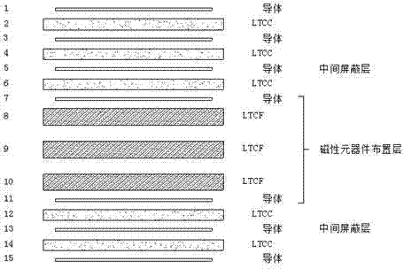
[0030] Example 2: figure 2 for in figure 1 Based on the modified "3C + 3F + 2C" composite laminated circuit substrate structure. The difference with Example 1 is that in figure 2 Among them, there is no conductor layer between the LTCF layers numbered 8 to 10, and the 3 layers of LTCF are directly stacked into a thicker ferrite layer to meet the design requirements.
Embodiment 3
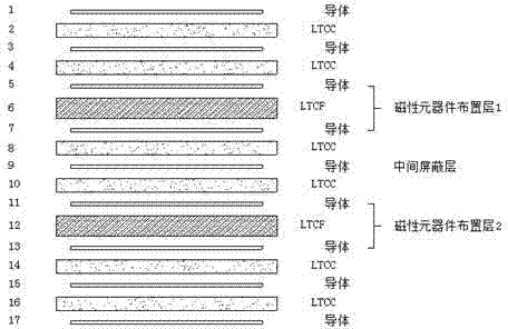
[0031] Example 3: image 3 It is a "2C + 1F + 2C + 1F + 2C" composite laminated circuit substrate structure. Among them, the conductors with serial numbers 5-7 and the LTCF layer constitute the "magnetic component layout layer 1", while the conductors with serial numbers 11-13 and the LTCF layer constitute the "magnetic component layout layer 2". Different magnetic component patterns are designed in the magnetic component layout layer 1 and the magnetic component layout layer 2 respectively, and they are separated by the "intermediate shielding layer" with the serial number 9; the remaining LTCC layers and conductor layers are used for the integrated design of capacitors , RF components and other circuit lines; the circuit patterns of each layer are connected through metal vias.
[0032] "3C" in the above description refers to 3 layers of continuous LTCC tiles, "3F" refers to 3 layers of continuous LTCF tiles, and so on. "Continuous" here means that there is no space between...
PUM
 Abstract
Description
Claims
Application Information
 - R&D Engineer
- R&D Manager
- IP Professional
- Industry Leading Data Capabilities
- Powerful AI technology
- Patent DNA Extraction
Browse by: Latest US Patents, China's latest patents, Technical Efficacy Thesaurus, Application Domain, Technology Topic, Popular Technical Reports.
© 2024 PatSnap. All rights reserved.Legal|Privacy policy|Modern Slavery Act Transparency Statement|Sitemap|About US| Contact US: help@patsnap.com


