Low cost high efficiency solar power plant

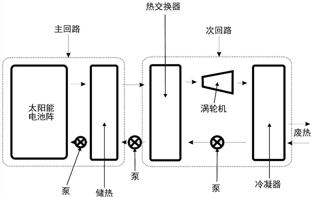
一种太阳能电池阵、太阳能的技术,应用在太阳能热发电、特定环境的太阳能集热器、太阳能热能等方向,能够解决有害全球变暖等问题

Active Publication Date: 2015-07-15
苏博德·维尔马
View PDF10 Cites 1 Cited by
  • Summary
  • Abstract
  • Description
  • Claims
  • Application Information

AI Technical Summary

Problems solved by technology

This leads to extremely harmful global warming unless the burning of fossil fuels is stopped immediately

Method used


Image

  • Low cost high efficiency solar power plant
  • Low cost high efficiency solar power plant
  • Low cost high efficiency solar power plant

Examples


Embodiment Construction

[0114] The following description with reference to the accompanying drawings is provided to assist in a comprehensive understanding of various exemplary embodiments of the invention as defined by the claims and their equivalents. It contains numerous specific details to assist in that understanding but these should be regarded as merely exemplary.

[0115] Accordingly, those of ordinary skill in the art will recognize that various changes and modifications of the various embodiments described herein can be made without departing from the scope and spirit of the invention. Also, descriptions of well-known functions and constructions are omitted for clarity and conciseness.

[0116] The terms and words used in the following description and claims are not limited to the bibliographical meanings, but, are merely used by the inventor to provide a clear and consistent understanding of the invention. Accordingly, it will be apparent to those skilled in the art that the description o...


PUM


Abstract

The present invention relates to a system and apparatus which is designed to use parabolic concentrator to focus sunlight onto a receiver which uses a coolant to carry the heat to the heat storage unit. The system comprises a primary loop comprising at least one solar array and at least one heat storage unit. The system further comprises a secondary loop operatively communicating with said primary loop. The solar array comprises plurality of reflector dish assemblies comprising reflector dish means whereby said dish means are arranged in close proximity to each other wherein said dish means being such that high sunlight concentration ratio is obtained for providing high conversion efficiency from heat to electricity.

Description

technical field [0001] The present invention relates to a very low cost and high efficiency system and device designed to use a parabolic concentrator to focus sunlight onto a receiver that uses a coolant to deliver heat to a thermal storage unit. A secondary circuit using water as a coolant extracts heat from the heat storage unit and uses it to run a turbine to generate electricity. Waste heat from the secondary loop can be re-used to run the desalination plant, or simply consumed to the environment. Background technique [0002] Currently, several systems for converting sunlight into electricity have been developed or are being developed. A brief description of these systems and their advantages and disadvantages is given below to better understand solar power generation. [0003] 1) Parabolic Trough: This was one of the first systems developed and is one of the most popular systems still in use in some countries. In such systems, a parabolic trough has a conduit throu...

Claims


Application Information

Patent Timeline
Patent Type & Authority Applications(China)
IPC IPC(8): F24J2/12F24J2/42F03G6/06F24J2/05F24J2/10F24S10/40F24S10/70F24S23/70F24S23/71F24S50/20F24S90/00
CPCF24J2/4612F24J2/5417F24J2/50F24J2/4647F24J2/5232F24J2/04Y02E10/42F28D20/0056F24J2/51F24J2/10F24J2/1057Y02E10/46F24J2/07F24J2/12F24J2/4621F24J2/24F03G6/067Y02E10/44F24J2/38F24J2/34F24J2/461F24S10/00F24S10/70F24S20/20F24S23/70F24S23/71F24S23/82F24S25/12F24S30/45F24S40/20F24S40/40F24S40/50F24S50/20F24S80/30F24S80/50F24S80/60Y02E10/47Y02E70/30Y02A40/22Y02E10/40Y02E60/14
Inventor 苏博德·维尔马
Owner 苏博德·维尔马
Why Eureka
Try Eureka