Bar mill

A wire rod and rolling mill technology, which is applied to the driving device for metal rolling mills, metal rolling, metal rolling, etc., can solve the problems of energy loss, high power of the main motor, and increased cost, so as to reduce investment and use The effect of maintenance cost, gear transmission pair reduction, and transmission chain path shortening

Inactive Publication Date: 2015-07-22
CHONGQING MAITUO TECH CO LTD
View PDF8 Cites 9 Cited by
  • Summary
  • Abstract
  • Description
  • Claims
  • Application Information

AI Technical Summary

Problems solved by technology

[0004] This method well ensures that the second flow rate between the racks is equal, but the continuous multiple racks are driven by a main motor, resulting in a huge power of the main motor, and the need to use a high-voltage motor, which greatly increases the cost, and this kind of High-voltage large motors and their electrical control device technologies are mostly monopolized in the market, with high costs and difficult maintenance, making it difficult to be popularized and used
[0005] In addition, this multi-rack centralized transmission method, because its transmission chain is too long, its no-load power even reaches about thousands of kilowatts, resulting in a huge loss of energy consumption, especially now that steel production enterprises are increasingly competitive and difficult to survive In some cases, this kind of transmission mode and rolling mill with high investment cost and large energy loss cannot meet the needs of cost reduction, energy saving and emission reduction.
[0006] In this kind of centralized transmission, the gear speed ratio of each rolling mill is fixed, and the gear cannot be changed. Only the frequency conversion of the motor can be used to meet the wide range of rolling speed requirements from about 20m / s to 110m / s, and it is difficult to give full play to the performance of the motor. Efficacy, that is, it is difficult to achieve an effective matching output of torque and speed by shifting gears during rolling, and it is necessary to amplify the power of the motor to meet the rolling demand, resulting in loss
At the same time, since the speed ratio between the racks is fixed and driven by one motor, when the wear amount of the roll ring of one of the racks is more, that is, the diameter of the roll ring becomes smaller, and the linear speed of the roll ring becomes smaller, resulting in a second flow rate. The second flow rate of the adjacent rolling mill is less than that of the adjacent rolling mill, and piles of steel are generated. At this time, because the speed ratio of the rolling mill is fixed, and it is driven by a motor, the roll ring must be replaced, or even the roll ring of multiple stands can be re-established. The relationship between the flow rate per second is equal, and the normal rolling of steel will cause a large loss of roll rings, many spare parts, difficult maintenance, and a corresponding increase in rolling costs

Method used


Image

  • Bar mill
  • Bar mill
  • Bar mill

Examples


Embodiment Construction

[0030] The following will clearly and completely describe the technical solutions in the embodiments of the present invention with reference to the accompanying drawings in the embodiments of the present invention. Obviously, the described embodiments are only some, not all, embodiments of the present invention. Based on the embodiments of the present invention, all other embodiments obtained by persons of ordinary skill in the art without making creative efforts belong to the protection scope of the present invention.

[0031] The core of the present invention is to provide a wire and rod rolling mill which is cost-effective.

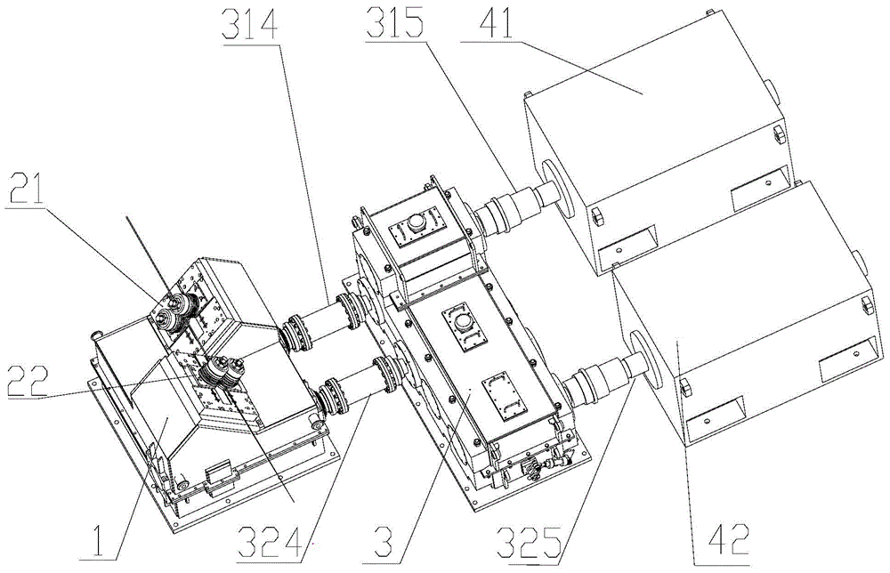
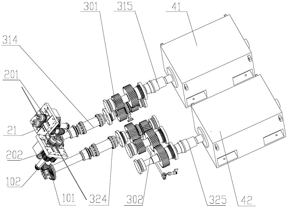
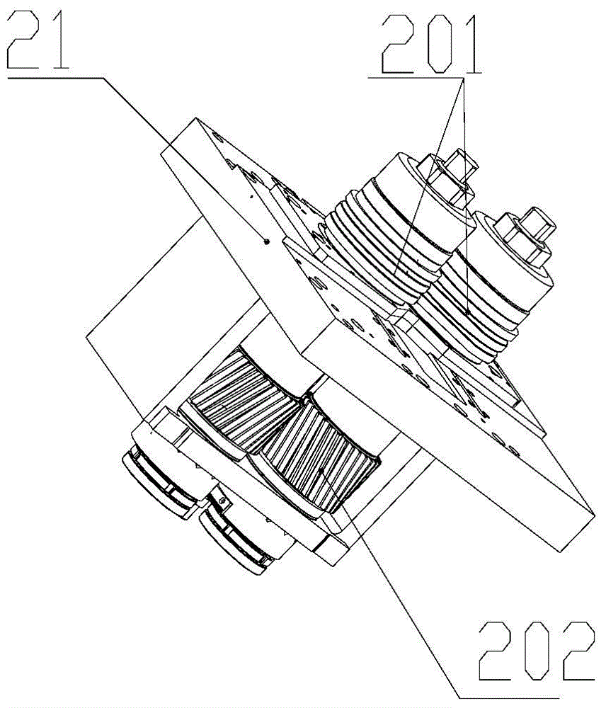
[0032] Please refer to Figure 1 to Figure 3 , Figure 1 to Figure 3 It is a structural schematic diagram, an internal structural diagram and a three-dimensional structural diagram of a roll box of a specific embodiment of a wire and bar rolling mill provided by the present invention.

[0033] The wire and bar rolling mill provided in this embodiment...


PUM


Abstract

The invention discloses a bar mill which comprises a first transmission device, a second transmission device, a first power device and a second power device. A first driving shaft and a first driven shaft are provided with at least two first gear pairs different in transmission ratio, and the first transmission device is further provided with a first gearing shifting device used for switching different first gear pairs to be fixedly connected with the first driving shaft or the first driven shaft. A second driving shaft and a second driven shaft are provided with at least two second gear pairs different in transmission ratio, and the second transmission device is further provided with a second gearing shifting device used for switching different second gear pairs to be fixedly connected with the second driving shaft or the second driven shaft. The first power device is connected with a first roller box through the first transmission device, and the second power device is connected with a second roller box through the second transmission device. According to the bar mill, each roller box is driven by one independent power device with small power, power transmission is carried out through the gear shifting devices, cost is greatly reduced, and the investment and use maintenance cost is greatly reduced.

Description

technical field [0001] The invention relates to the technical field of steel rolling equipment, in particular to a wire and bar rolling mill. Background technique [0002] As the main equipment in the steel hot rolling production line, the rolling mill is used to roll the blank into shape, such as for the rolling of threaded steel bars, round steel, etc., and usually passes through rough rolling, intermediate rolling, pre-finishing rolling, finishing rolling, etc. Passes are rolled to produce finished products. [0003] At present, due to the high rolling speed of the finishing mill used for wire rod rolling, the rolling mill usually adopts the racks arranged alternately with the top of the roll to realize the non-twist rolling of the rolled piece, reduce the vibration and facilitate the replacement of the roll, and due to the requirement of the machine The distance between the racks is small and the flow rate of each rack is required to be equal during rolling to avoid pil...

Claims


Application Information

Patent Timeline
Patent Type & Authority Applications(China)
IPC IPC(8): B21B35/12B21B1/16
Inventor 冯宗茂
Owner CHONGQING MAITUO TECH CO LTD
Why Eureka
Try Eureka