Monitoring method for vertical milling cutting vibration

A flutter and end milling technology, which is applied to measuring/indicating equipment, instruments, computer parts, etc., can solve the problems of sound signal interference, unsatisfactory guidance, and large impact on machine tool worktables, etc., to achieve accurate identification, The effect of preventing damage

Inactive Publication Date: 2015-07-22
CHANGZHOU COLLEGE OF INFORMATION TECH
View PDF4 Cites 27 Cited by
  • Summary
  • Abstract
  • Description
  • Claims
  • Application Information

AI Technical Summary

Problems solved by technology

[0003] Among the above signals, the sound signal can reflect the vibration generated by the interaction between the tool and the workpiece. The cutting force signal is one of the main sources of mechanical vibration in the machining process. The torque signal in the cutting process can also be used as an input signal. Each kind of information is Different methods are used to extract chatter features, so as to monitor cutting chatter and estimate tool wear; the sound signal can be obtained through a microphone, which is easy to implement, low in cost, and can reflect the change of the cutting state, but the sound signal is easily affected by the same workshop. interference from other processing equipment; in the process of cutting chatter, the change of the cutting force signal will be more obvious, which is conducive to the extraction

Method used


Image

  • Monitoring method for vertical milling cutting vibration
  • Monitoring method for vertical milling cutting vibration
  • Monitoring method for vertical milling cutting vibration

Examples


Embodiment Construction

[0029] Embodiments of the present invention are described in detail below, examples of which are shown in the drawings, wherein the same or similar reference numerals designate the same or similar elements or elements having the same or similar functions throughout. The embodiments described below by referring to the figures are exemplary only for explaining the present invention and should not be construed as limiting the present invention. On the contrary, the embodiments of the present invention include all changes, modifications and equivalents coming within the spirit and scope of the appended claims.

[0030] In the description of the present invention, it should be understood that the terms "first", "second" and so on are used for descriptive purposes only, and cannot be interpreted as indicating or implying relative importance. In the description of the present invention, it should be noted that unless otherwise specified and limited, the terms "connected" and "connect...


PUM


Abstract

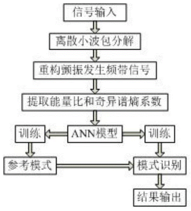
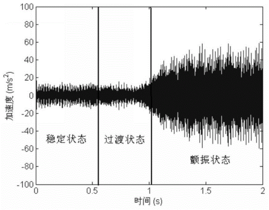
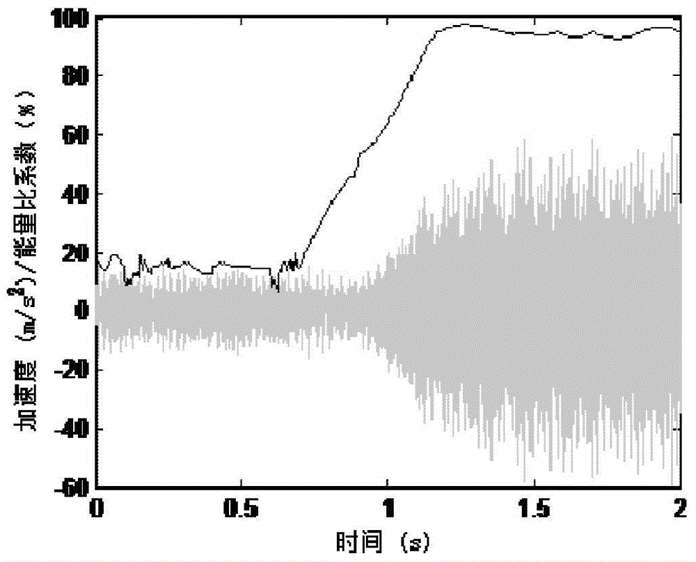
The invention provides a monitoring method for vertical milling cutting vibration. The monitoring method comprises the steps that in the process of acceleration signal obtaining, an acceleration sensor installed on a main shaft of a vertical milling cutting machine is used for collecting acceleration signals produced in the vertical milling cutting process, the acceleration signals are shown as the formula: X=[x(1), x (2),..., x(n)], n represents the signal length, and the acceleration signals comprise the stable state signals, the transition state signals and the vibration state signals, all of which are located in different frequency bands. According to the monitoring method for vertical milling cutting vibration, the acceleration signals are utilized as reflecting signals of cutting vibration, an energy ration coefficient and a singularity spectrum entropy coefficient are calculated based on the signals to serve as a training sample of a BP neural network, and a vibration monitoring result is finally obtained. Compared with a common vibration detecting method, the sign of the cutting vibration can be found earlier, precise recognition is achieved before sharp vibration, and irretrievable harm caused by sharp vibration to workpieces and machine tool components is prevented.

Description

technical field [0001] The invention relates to the technical field of end milling, in particular to a monitoring method for end milling chatter. Background technique [0002] The research on the mechanism and monitoring of cutting chatter can be traced back to 1946. In the early stage of research, it was believed that the occurrence of chatter was mainly due to the negative damping of the cutting system. With the deepening of research, it was found that cutting chatter was mainly caused by regeneration and mold caused by state coupling effects. In order to improve the stability of the machining process, it is necessary to conduct online monitoring of cutting chatter based on the monitoring signal of the machining process through feature extraction and classification technology. For the monitoring signal, the signal that is convenient to collect, less affected by the external environment and can reflect the nature of cutting chatter should be selected, usually including the...

Claims


Application Information

Patent Timeline
IPC IPC(8): B23Q17/12G06K9/66
CPCB23Q17/12B23Q2717/006G06V30/194
Inventor 王二化
Owner CHANGZHOU COLLEGE OF INFORMATION TECH
Why Eureka
Try Eureka