Rust removing machine special for petroleum pipeline

A technology for oil pipelines and rust removal machines, which is applied in the direction of grinding workpiece supports, grinders, metal processing equipment, etc. The effect of reducing the duty cycle

Inactive Publication Date: 2015-07-22
CHENGDU LAIBAO PETROLEUM EQUIP
View PDF7 Cites 8 Cited by
  • Summary
  • Abstract
  • Description
  • Claims
  • Application Information

AI Technical Summary

Problems solved by technology

[0003] In order to solve the defects of low efficiency of manual derusting, high operating intensity and easy to cause

Method used


Image

  • Rust removing machine special for petroleum pipeline
  • Rust removing machine special for petroleum pipeline

Examples


Example Embodiment

[0014] Example 1

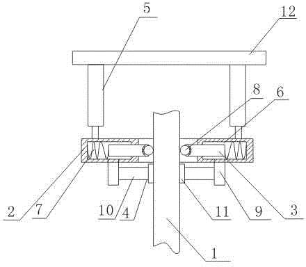
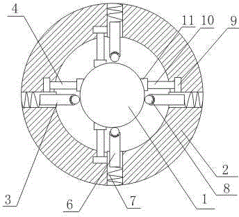
[0015] Such as figure 1 , figure 2 As shown, a derusting machine dedicated to petroleum pipelines includes an annular rotating plate 2 sleeved on the outer diameter of the oil drill pipe 1, and an annular cavity is opened on the inner wall of the annular rotating plate 2; A clamping device 3 arranged in the ring cavity and a rust removing device 4 fixed on the lower surface of the annular rotating plate 2; the clamping device 3 includes a support rod 6 slidably arranged in the ring cavity, and includes two ends connected to the ring cavity respectively The inner wall of the support rod 6 is connected to the spring 7 at the rear end of the support rod 6, and the front end of the support rod 6 passes through the opening of the ring cavity and is arranged outside the ring cavity, and further includes a universal ball 8 arranged at the front end of the support rod 6.

[0016] In this embodiment, when the annular rotating plate 2 is not sleeved on the oil drill pipe...

Example Embodiment

[0017] Example 2

[0018] In this embodiment, on the basis of embodiment 1, the rust removal device 4 includes a connecting block 9, a connecting rod 10 connected to the connecting block 9, and a grinding body 11 fixed at the end of the connecting rod 10. The side of the connecting block 9 is arranged at On the lower surface of the annular rotating plate 2.

[0019] The polishing body 11 in this embodiment can derust the oil drill pipe 1 when the annular rotating plate 2 moves up and down or rotates along the axis of the oil drill pipe 1, and the polishing plate using quartz stone has a better effect.

Example Embodiment

[0020] Example 3

[0021] On the basis of embodiment 1 or embodiment 2, this embodiment also includes a rotary table 12 arranged above the oil drill pipe 1, and a hydraulic cylinder 5 evenly arranged on the rotary table 12 around the axis of rotation of the rotary table 12. The piston rod is connected with the annular rotating plate 2.

[0022] The arrangement of the hydraulic cylinder 5 and the rotating table 12 in this embodiment can drive the annular rotating plate 2 to move up and down and rotate, without the need for staff to operate, the efficiency is high, and the work cycle is reduced.


PUM


Abstract

The invention provides a rust removing machine special for a petroleum pipeline. The rust removing machine special for the petroleum pipeline comprises an annular rotating plate arranged on the outer diameter of a petroleum drill stem in a sleeving mode, annular cavities are formed in the inner wall of the annular rotating plate, and the rust removing machine special for the petroleum pipeline further comprises clamping devices which are arranged in the corresponding annular cavities evenly around the center of the annular rotating plate and rust removing devices fixed on the lower surface of the annular rotating plate; each clamping device comprises a support rod, a spring and a universal ball, wherein each support rod is arranged in the corresponding annular cavity in a sliding mode, the two ends of each spring are connected with the inner wall of the corresponding annular cavity and the rear end of the corresponding support rod respectively, the front end of each support rod penetrates through an opening of the corresponding annular cavity and is arranged outside the corresponding annular cavity, and the universal balls are arranged at the front ends of the support rods. Accordingly, due to the fact that the springs and the universal balls are arranged, the rust removing machine special for the petroleum pipeline can be suitable for petroleum drill steams with different sizes.

Description

technical field [0001] The invention relates to a derusting device, in particular to a derusting machine specially used for oil pipelines. Background technique [0002] After the oil drill pipe is used, a dirt layer and a rust layer will be formed on the surface. During equipment maintenance, the oil drill pipe needs to remove the dirt layer and rust layer on the surface. Now, the dirt layer and rust layer are generally removed manually by hand-held grinders. However, the manual removal method has a long construction period, high operation intensity and extremely low efficiency. Furthermore, due to the existence of petroleum substances and rust substances on the surface of the used oil drill pipe, during grinding, the high temperature and high-speed rotation effect will easily cause the rust dust to be lifted into the air, causing construction workers to inhale the dust. Contents of the invention [0003] In order to solve the defects of low efficiency of manual descaling...

Claims


Application Information

Patent Timeline
IPC IPC(8): B24B27/033B24B41/06
CPCB24B27/033B24B41/067
Inventor 谭正怀
Owner CHENGDU LAIBAO PETROLEUM EQUIP
Why Eureka
Try Eureka