Low-speed safety aircraft capable of controlling flight attitude by aerodynamic force

A technology of flight attitude and aircraft, which is applied in the field of aviation aircraft, can solve the problems of complicated actions, single application, and oversimplification, and achieve the effect of simple and easy driving, removing bulkiness and cumbersomeness, and slowing down the speed of descent

Inactive Publication Date: 2015-07-22
顾一明
View PDF1 Cites 6 Cited by
  • Summary
  • Abstract
  • Description
  • Claims
  • Application Information

AI Technical Summary

Problems solved by technology

The wing flaps, ailerons, horizontal tails, and vertical tails of fixed-wing aircraft now play the role of attitude control in flight, and they all use large, unresponsive hydraulic or mechanical systems to complete the required mobilization. The structure of the wing is complicated and the movements are complicated, which greatly increases the structural weight of the aircraft and greatly increases the manufacturing cost and maintenance cost.
[0003] The general aircraft part has a large number of "low, slow and small" aircraft, including helicopters, drones, paramotors, gliders, airships, hot air balloons, etc. Some of these aircraft are too complex in structure, and some are too simple, with single application, poor safety performance, and difficult to operate. Those who require long-term professional training cannot be popularized

Method used


Image

  • Low-speed safety aircraft capable of controlling flight attitude by aerodynamic force
  • Low-speed safety aircraft capable of controlling flight attitude by aerodynamic force
  • Low-speed safety aircraft capable of controlling flight attitude by aerodynamic force

Examples


Embodiment Construction

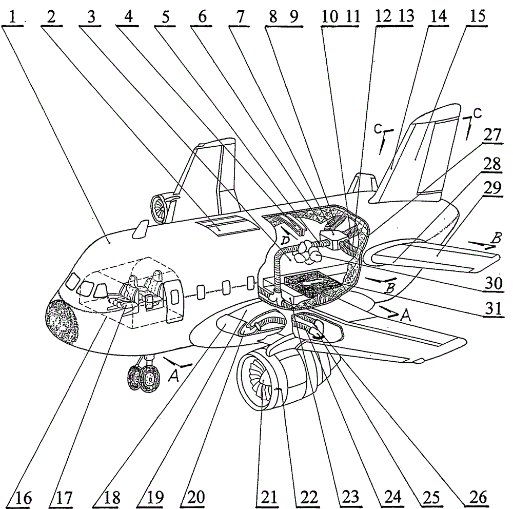
[0023] The following is attached figure 1 to attach Figure 6 The technical solution of the present invention is described in detail.

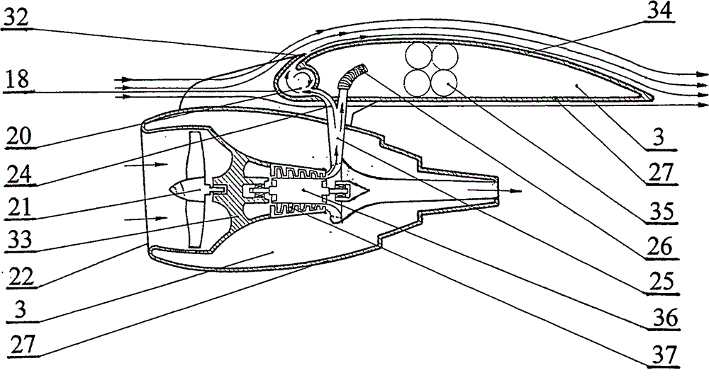
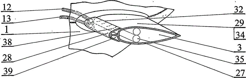
[0024] attached figure 1 , attached figure 2 As shown, the low-speed safety aircraft utilizing aerodynamic force to control flight attitude of the present invention comprises fuselage 1, wing 19, horizontal empennage 29, vertical empennage 15, engine 36, air compressor 37 to form, and engine 36 drives air compressor 37, output compression The air enters the vortex cavity 20 formed by the wing leading edge 18 from the flow divider 25 through the wing air supply pipe 24, and then reaches the airfoil 34 through the strip jet slot 32; the strip jet slot 32 is arranged at the radius of the wing leading edge 18 The arc transition part of the airfoil 34 , and the radius of the leading edge 18 of the wing along the long line of the arc of the airfoil 34 overlaps with the arc of the airfoil 34 , and leaves a strip jet slit 32 .

[0025] attached ...


PUM


Abstract

The invention discloses a low-speed safety aircraft capable of controlling the flight attitude by an aerodynamic force. The low-speed safety aircraft comprises a flexible aircraft, an engine, a gas compressor, a supply air distributor, vortex chambers, high-pressure gas cells, strip-shaped jet flow seams, helium airbags, a safety cabin and the like. Compressed gas in the gas compressor is ejected to airfoils through the strip-shaped jet flow seams arranged at the transition positions of leading edges and the airfoils of wings to generate a lift force and a push force, and is ejected to airfoils through the strip-shaped jet flow seams arranged at the transition positions of leading edges and the airfoils of a horizontal tail and a vertical tail to generate a wing effect to control the flight attitude. Through the application of a flight control principle and the combination with flexible body-wings, the helium airbags and the safety cabinet, the super-safe low-speed aircraft is formed. The low-speed safety aircraft has the advantages that fuel consumption is reduced greatly; piloting is easy; due to super-strong low-speed safety and controllability, the low-speed safety aircraft can be widely applied to prospecting, shooting, urban road monitoring, aerial advertising and the like; a super entertainment project suitable for the crowds which have firsthand experience of piloting a plane to flight, without pilot licenses, can be further developed.

Description

technical field [0001] The invention relates to aviation aircraft, in particular to the form of increased lift and flight attitude control of the aircraft. Background technique [0002] Since the Wright brothers made the first fixed-wing aircraft and successfully tested it in 1903, the take-off and landing modes of fixed-wing aircraft are usually by taxiing, that is, the thrust or pull of the engine makes the aircraft slide horizontally, and the wings move relative to the air. , according to the principle of the wing, due to the difference in the curvature of the upper and lower sides of the wing, the high-speed gliding aircraft wing makes the relatively static air flow through different distances on the upper and lower sides of the wing at the same time, and the longer the distance, the faster the flow velocity, according to Panulli Theorem, the wing will generate lift to make the aircraft fly off the ground. Therefore, the fixed-wing aircraft will bring speed through taxii...

Claims


Application Information

Patent Timeline
Patent Type & Authority Applications(China)
IPC IPC(8): B64C21/04B64C23/08B64C9/38B64C29/00
Inventor 顾一明
Owner 顾一明
Why Eureka
Try Eureka