
Winding shaft of sheets, winding method of sheets with a low tension, and air tight structure of piston used for such the winding method

A technology for winding shafts and pistons, which is applied in the direction of winding strips, piston rings, engine components, etc., and can solve problems such as complex structures and changes in support positions

Inactive Publication Date: 2015-07-22
TOSHIN CO LTD
View PDF7 Cites 0 Cited by
  • Summary
  • Abstract
  • Description
  • Claims
  • Application Information

AI Technical Summary

Problems solved by technology

In this configuration, the box is fitted into a recess formed on the outer peripheral surface of the collar, which complicates the structure, and a large centrifugal force acts on the collar when the rotating shaft rotates at a high speed. It is possible to change the support position

Method used


Image

  • Winding shaft of sheets, winding method of sheets with a low tension, and air tight structure of piston used for such the winding method
  • Winding shaft of sheets, winding method of sheets with a low tension, and air tight structure of piston used for such the winding method
  • Winding shaft of sheets, winding method of sheets with a low tension, and air tight structure of piston used for such the winding method

Examples


Embodiment Construction

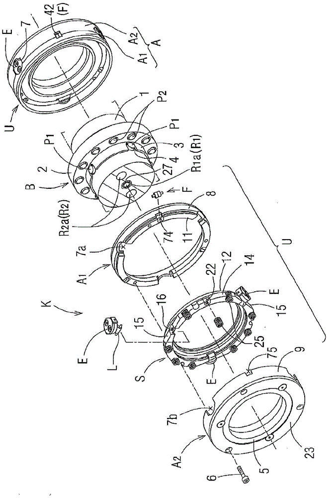
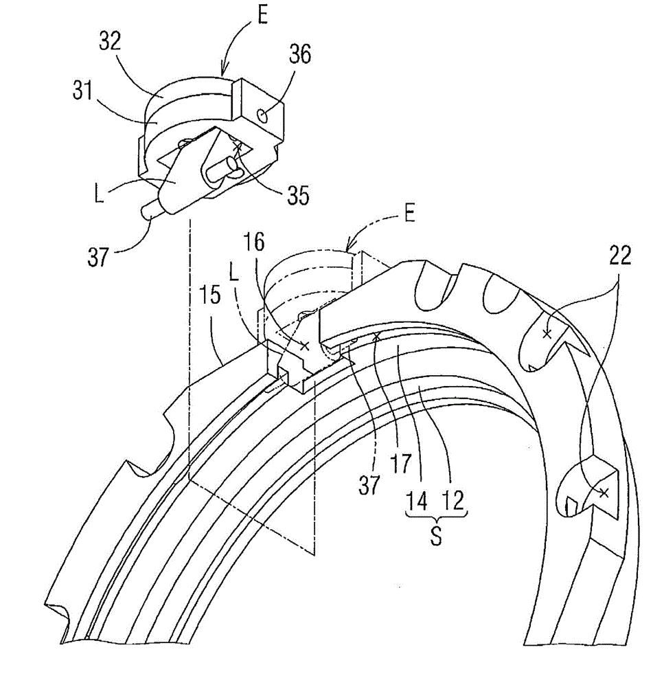
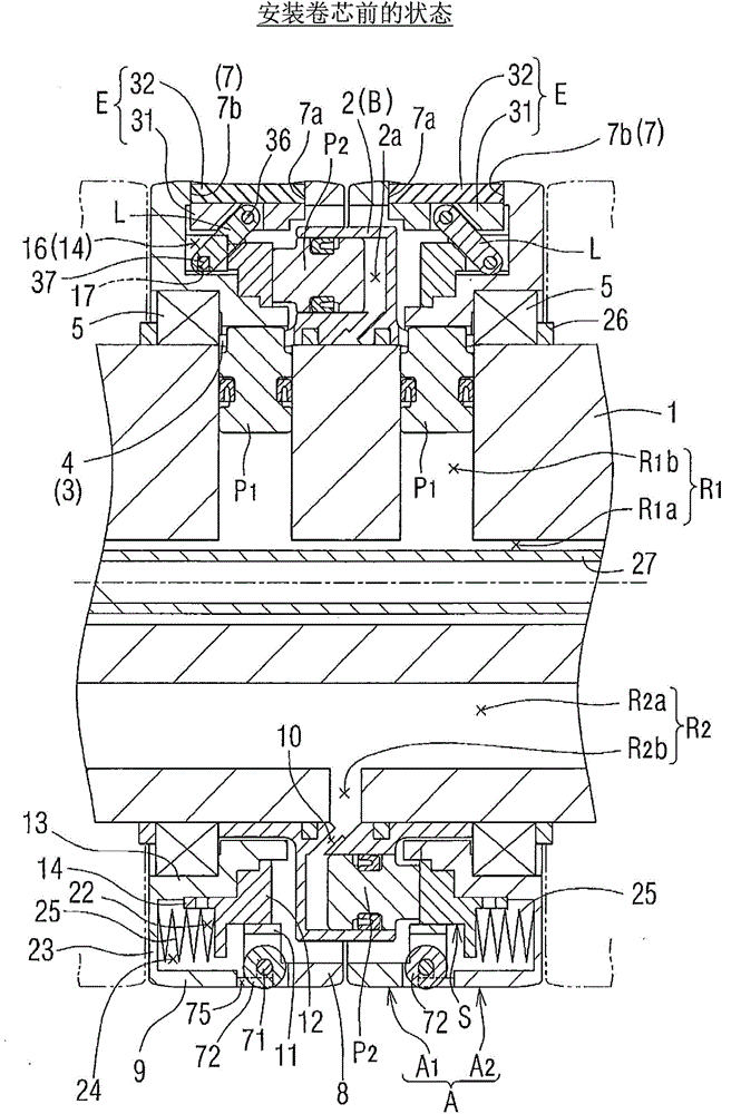
[0071] The present invention will be described in more detail below with a number of the most excellent examples. First refer to Figure 1 to Figure 7 The winding shaft K will be described. The winding shaft K is configured by attaching a plurality of winding units U to a shaft core 1, and a first passage R1 of compressed air for applying a pressing force to a first piston P1 to be described later is formed on the shaft core 1, and a first passage R1 for pressurized air to be described later is formed on the shaft core 1. The second piston P2 applies pushing force to the second channel R2 of compressed air. Such as Figure 3 ~ Figure 7 As shown, the first passage R1 includes an axial passage R1a and a plurality of radial passages R1b, the axial passage R1a is formed in the axial direction at the center of the shaft core 1, and the radial passage R1b communicates with the axial passage R1a And it is formed along the radial direction on the portion where the first piston P1 i...


PUM


Abstract

The invention provides a winding shaft K, which, through a simple structure, can reduce unnecessary power while enabling the winding shaft to rotate, of sheets. A plurality of winding units U are installed on the winding shaft K of the sheets in the axial direction of a shaft core part 1, and the winding units U are provided with a plurality of first pistons P1 installed in a cylinder B and a plurality of pistons P2 installed in the cylinder B. An outer peripheral ring A is divided into two parts in the axial direction of the shaft core part 1, clamping stop piece inserting holes 16 for clamping stop pieces E to be inserted in are formed through segmentation inserting holes respectively formed in sides, opposite to each other, of a first outer peripheral ring split body A1 and a second outer peripheral ring split body A2, the clamping stop pieces E are configured in the clamping stop piece inserting holes 16 in an inserting manner, and clamping stop pieces E and a slide ring S are connected through chain links L forming shifting mechanisms.

Description

technical field [0001] The present invention relates to a sheet winding shaft, a method of winding a sheet with low tension, and a piston sealing structure used for implementing the method. By stopping at the inner peripheral surface of the winding core, the winding core can be detached from the winding shaft and the sheet can be wound. [0002] Specifically, the sheet winding shaft according to the present invention is characterized in that, with respect to the outer peripheral ring constituting the sheet winding shaft, the installation of the above-mentioned locking piece or the installation of the small roller for Make it easy to take out the wound product with the sheet wound on the above-mentioned core; the method of winding the sheet with low tension according to the present invention and the piston sealing structure used for implementing the method are characterized in that: When winding the sheet under tension, the mechanical loss of the plurality of winding units con...

Claims


Application Information

Patent Timeline
Patent Type & Authority Applications(China)
IPC IPC(8): B65H75/18F16J9/00F16J9/20
CPCB65H18/04B65H18/08
Inventor 岩田哲三岛崇山村奈穗美近藤真由美
Owner TOSHIN CO LTD
Learn More