
Flood drainage system sealing structure with the function of draining underground spring water and tailings seepage

A technology for tailings and functions, applied in the field of plugging structures of tailings pond flood discharge systems, can solve problems such as large engineering volume, uncompact grouting, and low fluidity, and achieve small construction engineering volume, avoid seepage damage, and sand discharge. handy effect

Active Publication Date: 2016-05-11
CHANGSHA DESIGN & RES INST OF CHEM IND MIN
View PDF6 Cites 0 Cited by
  • Summary
  • Abstract
  • Description
  • Claims
  • Application Information

AI Technical Summary

Problems solved by technology

[0004] These two traditional sealing methods, no matter they are flexible or rigid, have three common problems. "Overwater" is based on "tight blockage", and eventually all the drainage functions of the original flood drainage system were abandoned, resulting in the seepage of tailings in the reservoir and underground spring water that could not be drained away by the flood drainage system, and were left in the In the reservoir, it can only be discharged through other flood drainage systems or seepage drainage systems; second, the chute line is long. According to the traditional thinking of "one overall sealing structure", whether it is flexible sealing or rigid sealing, The engineering volume is relatively large, the construction of sand washing and rolling stones is difficult, the fluidity is small, and the waste water is more, especially the cost of rigid plugging and grouting is relatively high; third, "tight sealing" is an ideal state. , because the structure is divided into two independent parts, the side wall tube bottom and the cover top, and there are cracks between the cover plates, so its integrity itself is worse than other structures, and it is easily deformed and broken by external loads and uneven foundation settlement. , the flexible sealing material itself is difficult to fit tightly with the pipe wall; and for rigid sealing, due to the limitation of engineering quantity and engineering cost, the grouting is often not dense
These all lead to the flow of water flowing into the gap between the chute wall and the plugging body, which may form a strip-shaped high-pressure body starting from the water-facing surface of the plugging body, forming a high-pressure penetration from the inside to the outside of the chute wall and surrounding tailings. It is easy to cause seepage damage to the surrounding tailings accumulation
[0005] In addition, the sealing structure of the traditional flood drainage system is an integral sealing structure, and the construction must have a sequence, which is often carried out from the bottom to the top.

Method used


Image

  • Flood drainage system sealing structure with the function of draining underground spring water and tailings seepage
  • Flood drainage system sealing structure with the function of draining underground spring water and tailings seepage
  • Flood drainage system sealing structure with the function of draining underground spring water and tailings seepage

Examples


Embodiment Construction

[0027] The present invention will be further described in detail below in conjunction with the accompanying drawings and specific embodiments.

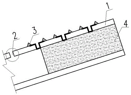
[0028] This embodiment includes an upstream blocking structure and a downstream blocking structure, refer to figure 1 , the upstream sealing structure includes a chute 1, a gap 2 is left between the cover plates of the chute 1, and non-woven geotextile I is filled in the gap 2, and the edge of the non-woven geotextile I extends to the cover plate of the chute 1, without The length of the woven geotextile I extending to the cover plate of the chute 1 is 30 cm, and the extended edge of the non-woven geotextile I is poured with cement mortar 3, and the extended edge of the non-woven geotextile I is fixed on the chute 1 through the cement mortar 3 The cover plate; the entrance section of the chute 1 is provided with a concrete block 4, and the specification of the non-woven geotextile I is 400g / m 2 .

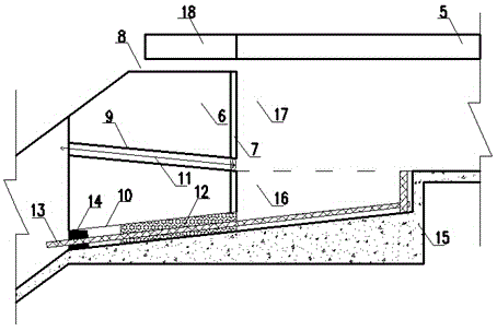
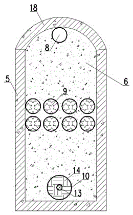
[0029] refer to figure 2 , ima...


PUM


Abstract

A flood drainage system blockage structure with an underground spring water and tailing seeping water drainage function comprises an upstream blockage structure and a downstream blockage structure. The upstream blockage structure comprises a chute, gaps are reserved between cover plates of the chute, the gaps are filled with non-woven geotechnical cloth I, and a concrete block is arranged at the inlet section of the chute. The downstream blockage structure comprises a culvert pipe, a concrete retaining wall is arranged at the outlet end of the culvert pipe, a concrete cover plate is arranged above the concrete retaining wall, a cement mortar plastering layer is arranged on one side face of the upstream side of the concrete retaining wall, and the concrete retaining wall is provided with an observation hole, an overflow hole and a sand washing hole; a grit chamber is arranged on the upstream side of the concrete retaining wall, a water passing area is located on the grit chamber, a concrete bottom plate is arranged at the bottom of the grit chamber, and the upper surface of the concrete bottom plate is a bevel. A second geotechnical cloth plug is arranged in the overflow hole, and a first geotechnical cloth plug is arranged at the inlet end of the sand washing hole. According to the flood drainage system blockage structure, flood cannot pass, but underground spring water and tailing seeping water can pass, no sand is leaked, construction quantity is small, cost is low, and construction period scheduling is flexible.

Description

technical field [0001] The invention relates to a plugging structure for a flood discharge system of a tailings pond, in particular to a plugging structure for a flood discharge system of a tailings pond with the function of discharging underground spring water and seepage of tailings. Background technique [0002] The flood drainage system is one of the key structures of the tailings pond. It is generally composed of water intake structures and drainage structures. The water intake structures are generally drainage wells or chutes, and the drainage structures are generally tunnels, chutes or culverts. When the service period of the flood drainage system is over and it is proved that it will no longer be used, the original flood drainage system must be blocked after the new flood drainage system is completed and put into use to end its discharge capacity and prevent it from becoming a tailings leakage channel . [0003] The sealing structure of the traditional flood drainag...

Claims


Application Information

Patent Timeline
Patent Type & Authority Patents(China)
IPC IPC(8): E02B7/00
CPCE02B3/16
Inventor 陈雯唐猛邓书申
Owner CHANGSHA DESIGN & RES INST OF CHEM IND MIN
Learn More