Reinforcing system and reinforcing method of wind power generation tower foundation ring foundation

A foundation ring and foundation technology, which is applied in the field of wind power tower foundation reinforcement, can solve problems such as foundation ring foundation cracking and damage, and achieve the effect of solving cracking, fatigue damage, and convenient construction

Active Publication Date: 2015-07-22
TONGJI UNIV ARCHITECTURAL DESIGN INST GRP CO LTD +2
View PDF6 Cites 21 Cited by
  • Summary
  • Abstract
  • Description
  • Claims
  • Application Information

AI Technical Summary

Problems solved by technology

This method can fundamentally solve the problem of cracking

Method used


Image

  • Reinforcing system and reinforcing method of wind power generation tower foundation ring foundation
  • Reinforcing system and reinforcing method of wind power generation tower foundation ring foundation
  • Reinforcing system and reinforcing method of wind power generation tower foundation ring foundation

Examples


Embodiment 1

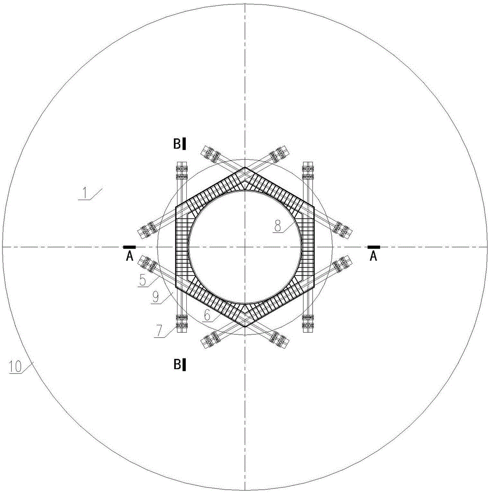
[0033] Such as Figure 1 to Figure 5 Shown, a kind of reinforcing system of foundation ring foundation of wind power generation tower, its this system comprises:

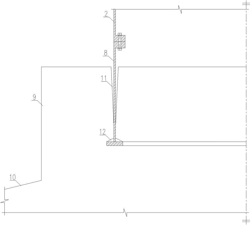
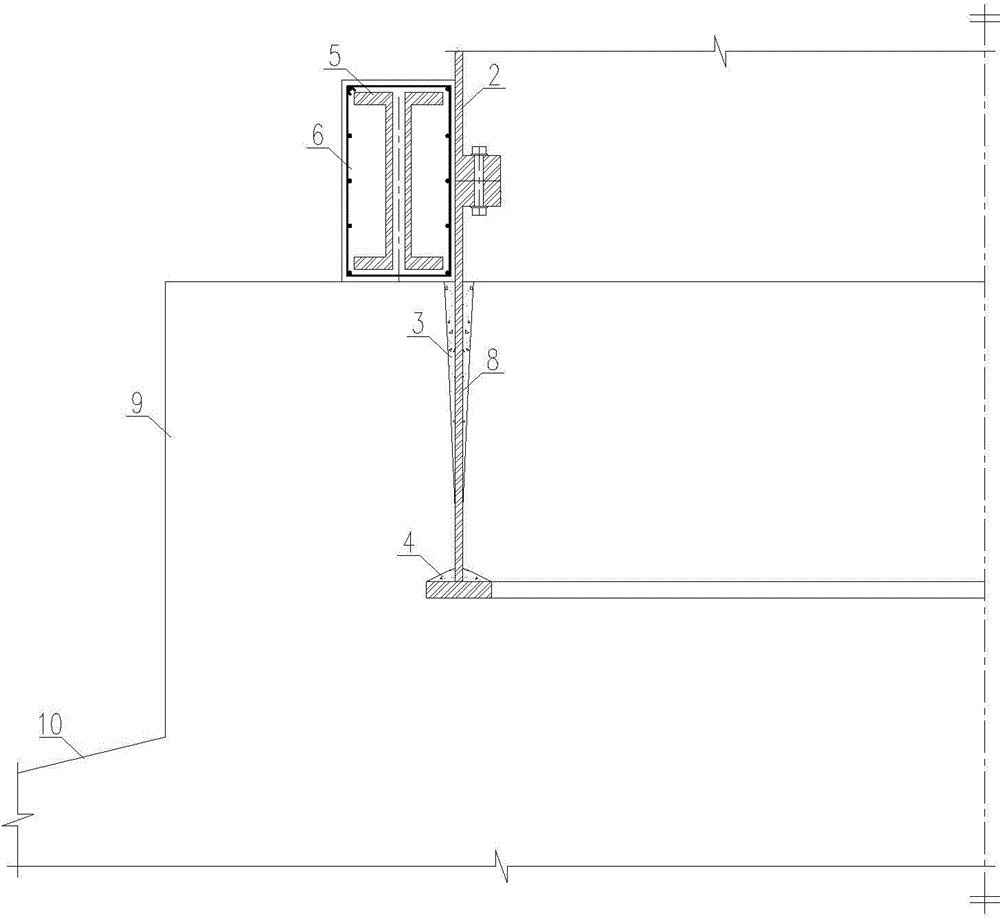
[0034] The foundation ring foundation (1) and the fan tower (2), the foundation ring foundation (1) includes the foundation bottom plate (10), the concrete column pier (9) connected to the foundation bottom plate (10), the lower end is embedded in The foundation ring (8) inside the concrete pier (9), the upper end of the foundation ring (8) is connected to the fan tower (2) through a flange;

[0035] There are 6 steel beams (5) arranged symmetrically on the outside of the foundation ring (8) and the top of the concrete pier (9), the intersections of two adjacent steel beams (5) are welded, and bolts are used in the middle of the steel beams (5) Splicing; 6 steel beams (5) form a regular hexagonal area around the foundation ring (8), and steel reinforced concrete beams (6) are poured around the regular hexagonal ste...

Embodiment 2

[0040] Such as Figure 1 to Figure 5 Shown, a kind of wind power generation tower foundation ring foundation reinforcement method is characterized in that, comprises the following steps:

[0041] a. Inject the high-strength grouting material into the damaged cavity (12) above the bottom flange of the foundation ring (8) to form a high-strength grouting material (4);

[0042] b. Inject epoxy resin into the crack (11) between the foundation ring (8) and the pier (9) to form epoxy resin caulking (3);

[0043] c. Drill a hole on the base plate (10), insert the lower anchor rod (15), inject epoxy resin (16) into the outer periphery of the lower part of the lower anchor rod (15), and put a PVC sleeve on the upper part of the lower anchor rod (15) ( 17), then pour the high-strength mortar block (18) on the top surface of the foundation base plate (10), then place the transfer beam (14) on the high-strength mortar block (18), tension the anchor rod (15) and place it Anchored on the tr...


PUM


Abstract

The invention relates to a reinforcing system and reinforcing method of a wind power generation tower foundation ring foundation. The system comprises the foundation ring foundation (1) and a draught fan tower drum (2). The foundation ring foundation (1) comprises a foundation bottom plate (10), a concrete column pier (9) and a foundation ring (8), and the foundation ring (8) is connected with the draught fan tower drum (2). Steel beams (5) are symmetrically arranged on the outer side of the foundation ring (8) and on the top of the concrete column pier (9), the steel beams (5) surround the foundation ring (8) to form a regular-hexagon-shaped area, and steel-reinforced concrete beams (6) are poured around the regular-hexagon-shaped steel beams (5) and on the outer side of the foundation ring (8). The two ends of the steel beams (5) are connected with prestress anchor rod assemblies (7), and the lower ends of the stress anchor rod assemblies (7) are anchored in the foundation bottom plate (10). Pre-tension force is applied to a prestress anchor rod, so that pre-compressive stress is generated on concrete around the foundation ring, and accordingly the crack problem of the foundation ring foundation caused by fatigue can be fundamentally solved.

Description

technical field [0001] The invention belongs to the technical field of wind power generation tower foundation reinforcement, and in particular relates to a wind power generation tower foundation ring foundation reinforcement system and a reinforcement method thereof. Background technique [0002] At present, the buried tower foundation has a certain share in the domestic wind power market. However, the foundation of the tower is limited by the depth of the foundation, resulting in the buried foundation of the buried section being too shallow, only about 0.3 to 0.4 times the diameter of the wind turbine tower. According to Article 8.4.15 of "Code for Design of Steel Structures" (GB50017-2003), the minimum insertion depth of the plug-in column foot is 1.5d (d is the outer diameter of the circular pipe column), while the actual depth of the foundation ring is only 0.3 d~0.4d is far less than 1.5d. Due to the shallow buried depth of the tower, the bending resistance provided b...

Claims


Application Information

Patent Timeline
IPC IPC(8): E02D27/42E02D37/00
Inventor 何桂荣马逸鹄
Owner TONGJI UNIV ARCHITECTURAL DESIGN INST GRP CO LTD
Why Eureka
Try Eureka