Structure of centrifugal fan impeller

A centrifugal fan and impeller technology, applied in mechanical equipment, machines/engines, liquid fuel engines, etc., can solve the problems of low production efficiency, high cost, complex processing technology, etc., and achieve the effect of improving performance and increasing filtration capacity

Inactive Publication Date: 2015-07-22
NINGBO FOTILE KITCHEN WARE CO LTD
View PDF5 Cites 14 Cited by
  • Summary
  • Abstract
  • Description
  • Claims
  • Application Information

AI Technical Summary

Problems solved by technology

[0005] However, the above-mentioned patent connects two impellers. First, two separate impellers must be made, and then the impellers are combined. The processing technology is complicated, the cost is high, and the production efficiency is low.

Method used


Image

  • Structure of centrifugal fan impeller
  • Structure of centrifugal fan impeller
  • Structure of centrifugal fan impeller

Examples


Embodiment 1

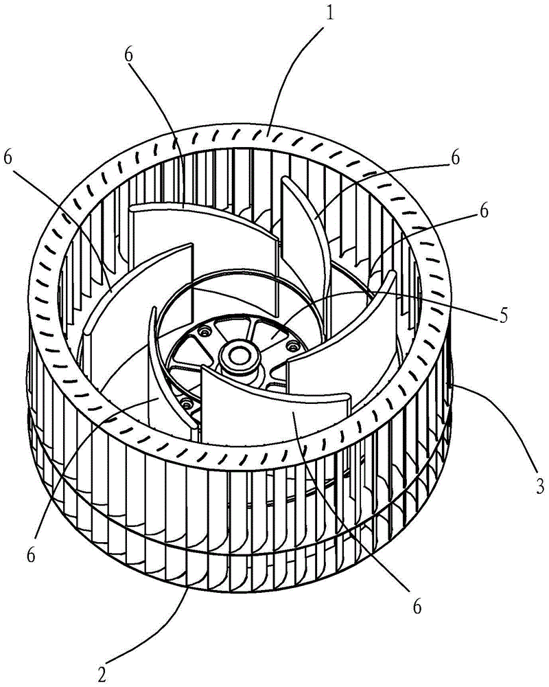
[0022] Such as figure 1 and figure 2 Shown is the centrifugal fan impeller structure in Embodiment 1 of the present invention, which has a front ring 1 and a rear ring 2, 60 blades 3 are fixed between the front ring 1 and the rear ring 2, and the outer ring blades 3 and the front ring 1 And the rear ring 2 is all fixed together by existing conventional riveting methods. A middle disc 4 is also arranged between the front ring 1 and the rear ring 2, and the center of the middle disc 4 is fixed with a wheel disc 5 for installing a motor by a rivet. The outer edge of the middle plate 4 is provided with a blade slot 42a corresponding to the blade. The blade 3 passes through the blade slot of the middle plate 4 and the blade 3 is stuck in the blade slot through the deformation of the blade slot, thereby realizing the blade slot. 3 and the fixation of the middle plate 4. The deformation of the blade slot is achieved by rolling the outer ring of the middle disc 4 to be radially st...

Embodiment 2

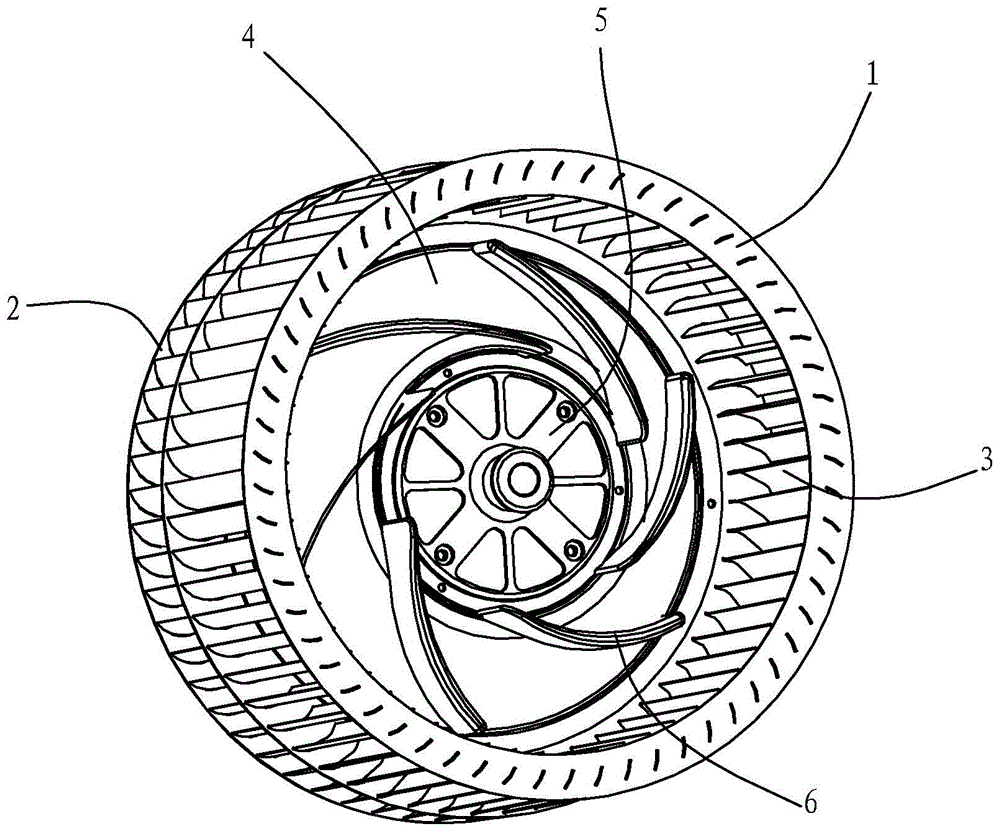
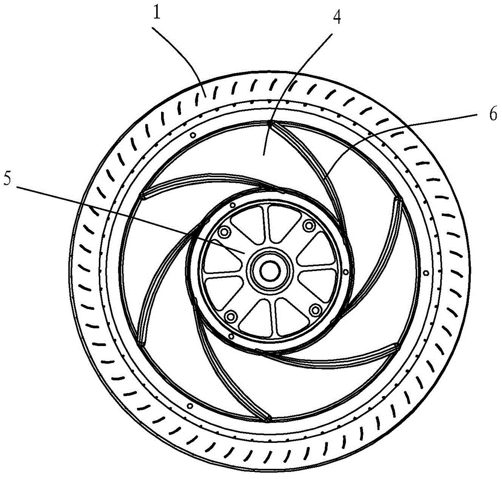
[0027] Different from Embodiment 1, the central disk 4 is in the shape of a flat plate, and the inner ring blades 6 are evenly distributed in a spiral shape in the radial direction of the central disk. see Figure 4 , 5 shown.


PUM


Abstract

The invention belongs to the technical field of impeller, and discloses a structure of a centrifugal fan impeller. The structure of the centrifugal fan impeller is provided with a front ring (1) and a rear ring (2). Outer-ring blades (3) are fixed between the front ring (1) and the rear ring (2), and a central disk (4) is further arranged between the front ring (1) and the rear ring (2). A wheel disk used for the installation of a motor is arranged at the central position of the central disk (4). The outer-ring blades (3) penetrate through a blade inserting groove at the outer edge of the central disk (4) and are fixed together with the central disk (4). The structure of the centrifugal fan impeller is characterized in that inner-ring blades (6) distributed in the radial direction of the central disk (4) are distributed on the central disk (4). The structure of the centrifugal fan impeller is provided with two layers of blades, preposed prewhirl can be generated in the inner-ring blades before air flow entering an outer-layer passageway, acting is conducted on the airflow entering the inside of the fan through the inner-ring blades, the speed and static pressure of the airflow at an inlet can be improved, and thereby the performance of the whole fan is improved.

Description

technical field [0001] The invention belongs to the technical field of impellers, in particular to a centrifugal fan impeller structure. Background technique [0002] Most of the impellers used in the market today are single impellers. When this type of impeller rotates, the air is fed from one side of the opening. It is relatively large in order to generate a large single-sided air intake. When it is applied to a small space, such as the internal space of the range hood, the external size of the range hood will increase, which not only affects the appearance, but also wastes materials and costs more. high. [0003] Moreover, the current traditional multi-blade centrifugal fan impellers generally only have one layer of blades, and the blades are characterized by short blades that are evenly distributed along the outer edge of the impeller. The pressure and velocity of the airflow on the circumference of the impeller are not evenly distributed; and because the diameter of t...

Claims


Application Information

Patent Timeline
Patent Type & Authority Applications(China)
IPC IPC(8): F04D29/28F04D29/70
CPCF04D29/283F04D29/30
Inventor 李斌任树栋茅忠群诸永定
Owner NINGBO FOTILE KITCHEN WARE CO LTD
Why Eureka
Try Eureka