Oil pump tightness performance test and leakage loss detection system and test device
A technology of sealing performance and detection system, which is applied in the direction of liquid tightness measurement using liquid/vacuum degree, pump test, and by measuring the increase and deceleration rate of fluid, etc. It can solve the problem of lack of multiple oil well pump detection solutions, which affect test efficiency, The low degree of mechanization and other problems can reduce the impact, ensure the safety of the system and improve the adaptability
- Summary
- Abstract
- Description
- Claims
- Application Information
AI Technical Summary
Problems solved by technology
Method used
Image
Examples
Embodiment approach 1
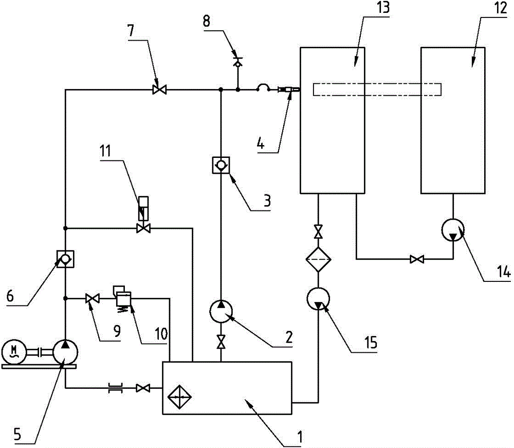
[0041] figure 1 It is a system schematic diagram of an embodiment of the oil well pump sealing performance test and leakage detection system of the present invention. refer to figure 1 As shown, the inlet of the low-pressure pump 2 is connected to the oil suction tank 1 through a pipeline, the outlet of the low-pressure pump 2 is connected to the inlet of the first one-way valve 3, and the outlet of the first one-way valve 3 is connected to the pressure test joint 4; the inlet of the high-pressure pump 5 is connected to the pipeline It is connected to the oil suction tank 1, the outlet of the high-pressure pump 5 is connected to the inlet of the second one-way valve 6, the outlet of the second one-way valve 6 is connected to the inlet of the first on-off valve 7, and the outlet of the first on-off valve 7 is connected to the pressure test joint 4; the pressure test joint The pressure measuring contact 8 is set on the front end pipeline of 4; the outlet of the overflow valve 1...
Embodiment approach 2
[0059] figure 2 With figure 1 A structural schematic diagram of an embodiment of the test device used in conjunction with the sealing performance test of the oil well pump, the leakage detection system and the supporting test device. The first oil collection tank 12 is provided at the rear of the frame 20, corresponding to the end position of the oil pump to be tested. The second oil collection tank 13 is arranged at the head end of the frame 20, below the connection port between the oil well pump and the pressure test joint 4. The first delivery The pump 14 is arranged on the frame 20, the first oil collecting tank 12 is connected with the inlet of the first delivery pump 14 through the pipeline, and the outlet of the first delivery pump 14 is connected with the second oil collecting tank 13 through the pipeline.
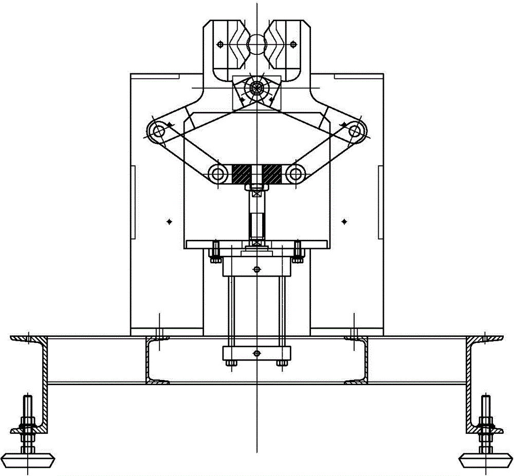
[0060] The frame 20 is provided with clamps 22 near both ends, and the test and test objects can be fixed by using the clamps. image 3 It is a schematic diagra...
Embodiment approach 3
[0066] Image 6 With figure 1 A structural schematic diagram of another embodiment of the test device used in conjunction with the sealing performance test of the oil well pump, the leakage detection system and the supporting test device. The types of oil pumps are different, and their lengths are also different. In order to make the test device adaptable to oil well pumps of different lengths, a traveling trolley 24 is provided on the frame, and the traveling trolley 24 can reciprocate along the frame. The traveling trolley is provided with The first oil collecting tank 23, the oil control mechanism 21, and the feeding and discharging mechanism 23 are respectively set. The setting of walking trolley 24 has enlarged the operating performance of test device, and it can be tested for oil well pumps with different lengths.
[0067] At the same time, a clamp 22 can also be set on the walking trolley, so as to facilitate the transportation and fixing of the tested object.
[006...
PUM
 Abstract
Description
Claims
Application Information
 - R&D
- Intellectual Property
- Life Sciences
- Materials
- Tech Scout
- Unparalleled Data Quality
- Higher Quality Content
- 60% Fewer Hallucinations
Browse by: Latest US Patents, China's latest patents, Technical Efficacy Thesaurus, Application Domain, Technology Topic, Popular Technical Reports.
© 2025 PatSnap. All rights reserved.Legal|Privacy policy|Modern Slavery Act Transparency Statement|Sitemap|About US| Contact US: help@patsnap.com


