Cable air-drying device

An air-drying device and cable technology, used in cable/conductor manufacturing, circuits, electrical components, etc., can solve the problems of occupying a large space, air-cooled lines cannot guarantee the drying effect of cable products, and dripping on the bottom, etc., to shorten the drying time. time, prolonging the stroke and residence time, and reducing the effect of water attachment

Inactive Publication Date: 2015-07-22
ANHUI HONGYI CABLE GROUP
View PDF7 Cites 7 Cited by
  • Summary
  • Abstract
  • Description
  • Claims
  • Application Information

AI Technical Summary

Problems solved by technology

Conventional air drying methods generally use cold air drying; in the cold air drying process, in order to avoid that the length of the air cooling line is not enough to ensure the drying effect of the cable products, the length of the cold air line is generally extended, and cold air is added on both sides of the cold air line In this way, it will occupy a large space, resulting in a waste of space, and in the drying process, the water droplets attached to the surface of the cable will drop to the bottom, resulting in water accumulation on the ground.

Method used


Image

  • Cable air-drying device
  • Cable air-drying device
  • Cable air-drying device

Examples


Embodiment Construction

[0020] Below, the technical solution of the present invention will be described in detail through specific examples.

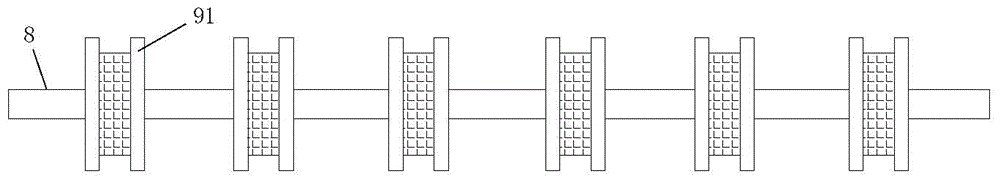
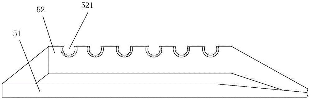
[0021] like Figure 1-4 as shown, figure 1 It is a structural schematic diagram of a cable air-drying device proposed by the present invention; figure 2 It is a schematic diagram of the assembly structure of the horizontal column and the guide wheel in a cable air-drying device proposed by the present invention; image 3 It is a structural schematic diagram of the water control tank in a cable air-drying device proposed by the present invention; Figure 4 It is the structural intention of the limit pressing bar in a cable air-drying device proposed by the present invention.

[0022] refer to Figure 1-4 , a kind of cable air-drying device that the embodiment of the present invention proposes, comprises: box body 1, air inlet pipe 2 and blowing device 3, wherein, the top of box body 1 feed inlet is provided with first guide wheel 12, box body 1 exits The ...


PUM


Abstract

The invention discloses a cable air-drying device. The cable air-drying device comprises a box body, an air inlet pipe and an air blast device. A wire press column is arranged in the portion, below a wire inlet, of the box body. A water control tank is arranged on one side of the wire press column, one end of the water control tank is fixed to the inner wall of the box body, and the other end of the water control tank penetrates through the box body and stretches out of the box body. The height of a first tank side of the water control tank in the direction of being close to the wire press column is smaller than that of a second tank side of the water control tank in the direction of being far away from the wire press column, a limiting press rod is arranged between the first tank side and the second tank side, and a plurality of notches which allow cables to pass through are formed in the second tank side in parallel. A guide column is arranged on one side of the wire outlet end of the water control tank, a plurality of transverse columns which are arranged in the longitudinal direction and the transverse direction are arranged below the guide column, and a plurality of wire guide wheels are installed on the transverse columns. One end of the air inlet pipe is connected with the air blast device, and the other end of the air inlet pipe stretches into the box body through an air inlet. According to the cable air-drying device, the effect that the surfaces of the cables are rapidly dried is achieved under the condition that the length of a cold air wire is not increased, and the phenomenon of water accumulation on the ground cannot happen.

Description

technical field [0001] The invention relates to the technical field of cable processing, in particular to a cable air-drying device. Background technique [0002] At present, in the process of cable processing, the insulating material outside the cable core can only be attached to the outside of the conductor core of the cable after being in a molten state, so that the cable with the insulating layer must be cooled by cold water to make the insulating layer on it from the molten state. change to the cross-linked state. The cables that have been cooled by cold water need to be air-dried. The conventional air-drying method generally adopts cold air drying; in the process of cold air drying, in order to avoid that the length of the air-cooling line is not enough to ensure the drying effect of the cable products, the length of the cold air line is generally extended, and cold air is added on both sides of the cold air line In this way, a large site will be occupied, resulting ...

Claims


Application Information

Patent Timeline
Patent Type & Authority Applications(China)
IPC IPC(8): H01B13/30
Inventor 陶成富吴本长
Owner ANHUI HONGYI CABLE GROUP
Why Eureka
Try Eureka