Vacuum sole pressing shoe making device structure

A device structure and vacuum pressure technology, which is applied in the direction of shoemaking machinery, footwear, and adhesive shoe parts, can solve the problems of poor processing stability and bonding stability, and achieve good bonding stability and processing stability.

Inactive Publication Date: 2015-07-29
东莞市良强机械有限公司
View PDF6 Cites 1 Cited by
  • Summary
  • Abstract
  • Description
  • Claims
  • Application Information

AI Technical Summary

Problems solved by technology

[0004] In view of the problems of poor processing stability and combination stability of conventional shoe-making sole-pressing devices, the present invention completes the structure of the vacuum sole-pressing shoe-making device of the present invention

Method used


Image

  • Vacuum sole pressing shoe making device structure
  • Vacuum sole pressing shoe making device structure
  • Vacuum sole pressing shoe making device structure

Examples


Embodiment Construction

[0033] In order to enable your examiners to further understand the structure, features and other purposes of the present invention, the following preferred embodiments are attached to the drawings in detail as follows, but the embodiments described in this illustration are for illustration purposes only. It is not the only restriction on the patent application.

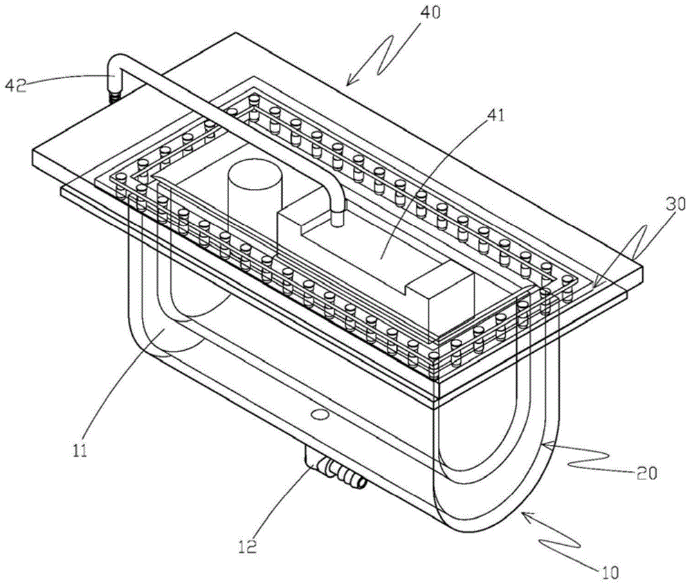
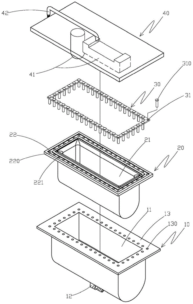
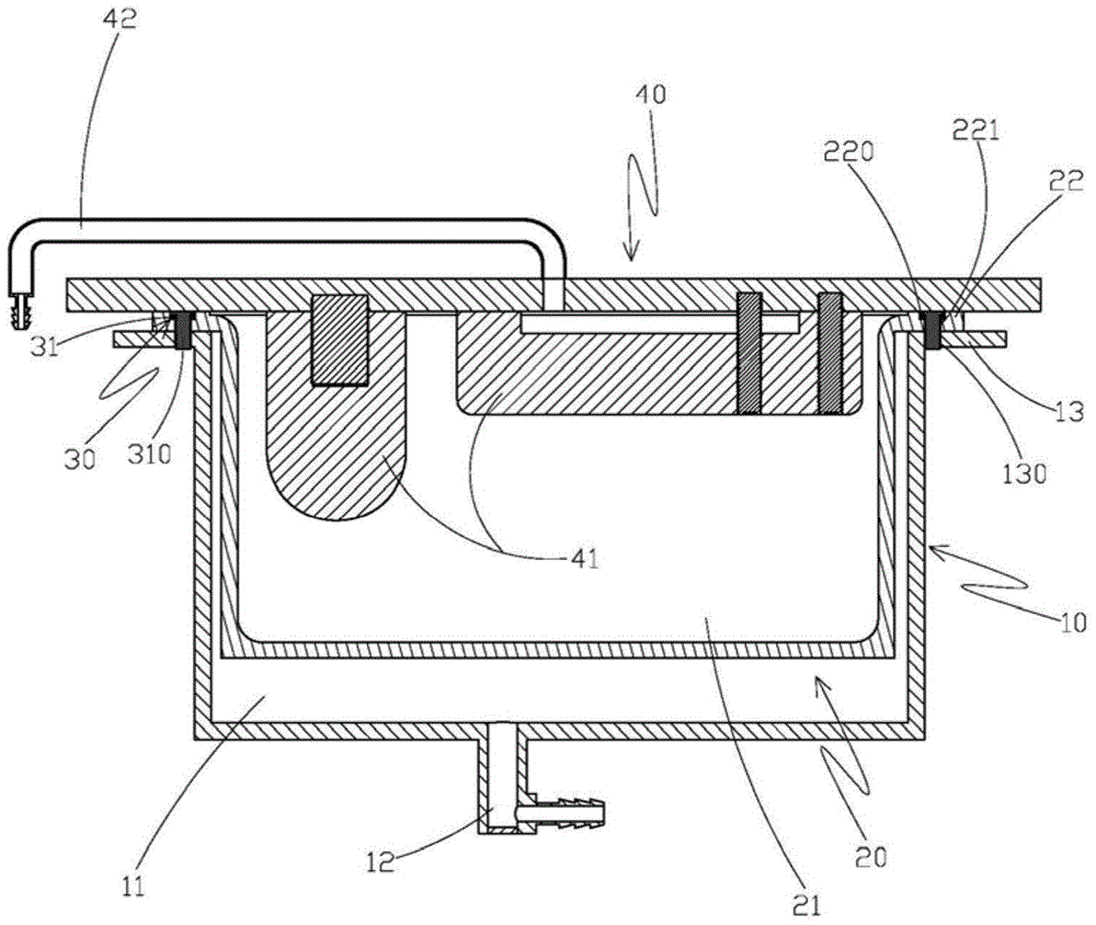
[0034] Please refer to Figures 1 to 3 As shown, it is a reference diagram of the three-dimensional combination, three-dimensional decomposition and side view section of the structure of the vacuum bottom shoemaking device of the present invention, which includes:

[0035] A base body 10, the base body 10 is provided with a cavity 11, and the bottom side of the base body 10 is connected with the cavity 11, and an air inlet duct 12 is provided, and the opening edge ring of the top side of the base body 10 is provided with an outer flange 13 , the outer flange 13 is provided with several coupling holes 130 at intervals...


PUM


Abstract

The invention discloses a vacuum sole pressing shoe making device structure. A shoe body containing a shoe last is placed into a containing groove in an elastic container, air is guided into an air inlet duct of a base body, so that the elastic container is pushed by the guided air, the air is sucked from an exhaust duct in a top cover, so that the elastic container is contracted into a vacuum state, gumming is arranged on the top face of a shoe sole, the shoe body is squeezed when the elastic container is contracted, the shoe sole and an upper of the shoe body are pressed by lateral and longitudinal contraction force, so that the shoe sole and the upper are stably combined, looseness of joint edges of the shoe sole and the upper can be avoided, the problems such as gum overflow and shoe body deformation caused by pressurization in the machining process are solved, and better machining stability and combining stability are achieved.

Description

technical field [0001] The invention relates to a structure of a vacuum sole-pressing shoe-making device, in particular to one used in the technical field of the shoe-making device. Background technique [0002] According to the currently known shoe-making bottom pressing device, its bottom pressing device is composed of a base, a pressing plate and a longitudinal driving device. The end of the longitudinally extending shaft of the driving device is fixedly combined with the top side of the pressure plate, and there is a free space between the pressing body and the base on the bottom side of the pressure plate. By placing the shoe body with the shoe last on the base, when the longitudinal When the driving device is driven, the longitudinal extension axis extends downward, and at the same time, the pressing plate moves downward, so that the pressing body on the bottom side of the pressing plate is pressed on the shoe body, so that the pressing plate exerts a downward pressing...

Claims


Application Information

Patent Timeline
Patent Type & Authority Applications(China)
IPC IPC(8): A43D25/047
Inventor 赖森明
Owner 东莞市良强机械有限公司
Why Eureka
Try Eureka