Method for preparing antifriction wear-resistant coating on metal matrix surface

A technology for metal substrates and wear-resistant coatings, applied in metal material coating processes, devices for coating liquid on surfaces, coatings, etc., can solve problems such as poor bonding force, coating damage, hard wear-resistant coatings, etc. problems, to achieve long life, prevent the accumulation of plastic deformation, and prevent the effect of eccentric seizure

Active Publication Date: 2015-10-07
NORTHWEST INSTITUTE FOR NON-FERROUS METAL RESEARCH
View PDF2 Cites 34 Cited by
  • Summary
  • Abstract
  • Description
  • Claims
  • Application Information

AI Technical Summary

Problems solved by technology

Due to the hard material of a single wear-resistant coating, cracks often exist on the surface of the coating. Cracks are the cause of fatigue shedding during the wear process. Once cracks occur, they will cause irreparable damage to the moving parts. Due to the soft material and poor bonding force with the substrate, the coating will be damaged in the early stage under extremely heavy load conditions, and the application is restricted. Therefore, in actual production, it is necessary to consider both wear resistance and friction reduction. performance matching problem

Method used


Image

  • Method for preparing antifriction wear-resistant coating on metal matrix surface
  • Method for preparing antifriction wear-resistant coating on metal matrix surface
  • Method for preparing antifriction wear-resistant coating on metal matrix surface

Examples


Embodiment 1

[0032] This embodiment includes the following steps:

[0033] Step 1. Mix the wear-resistant powder and metal powder evenly at a mass ratio of 1:5 to obtain cladding powder. The wear-resistant powder is tungsten carbide powder, and the metal powder is nickel powder;

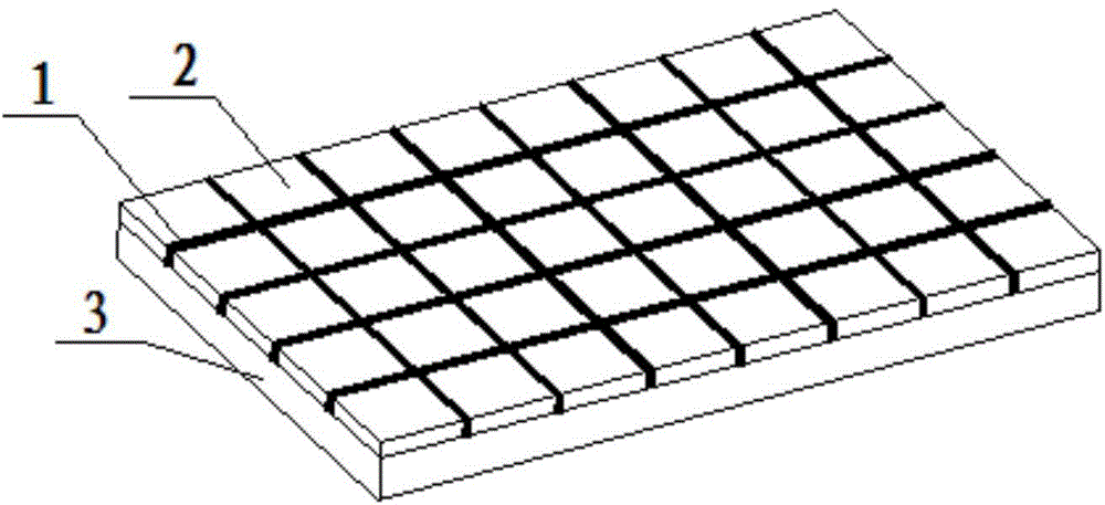
[0034] Step 2. Using the method of synchronous powder feeding, according to the preset grid-shaped scanning trajectory, under the argon protective atmosphere with a pressure of 0.01MPa, laser cladding the cladding powder described in step 1 on the surface of the metal substrate 3 , forming a plurality of cladding strips 1 that intersect horizontally and vertically, and a plurality of cladding strips 1 that intersect vertically and horizontally form a cladding skeleton with a grid structure; the laser power of the laser cladding is 6153W, and the spot diameter is 3mm. The powder feeding rate is 35g / min, and the scanning speed is 25mm / s; the metal substrate 3 is a TC4 titanium alloy substrate, the metal substrate 3...

Embodiment 2

[0040] This embodiment includes the following steps:

[0041] Step 1, uniformly mix wear-resistant powder and metal powder at a mass ratio of 1:10 to obtain cladding powder, the wear-resistant powder is titanium carbide powder, and the metal powder is iron powder;

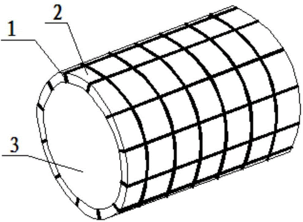
[0042] Step 2. Using the method of synchronous powder feeding, according to the preset grid-like scanning trajectory, under the argon protective atmosphere with a pressure of 0.1MPa, laser cladding the cladding powder described in step 1 on the surface of the metal substrate 3 , forming a plurality of cladding strips 1 that intersect horizontally and vertically, and a plurality of cladding strips 1 that intersect vertically and horizontally form a cladding skeleton with a grid structure; the laser power of the laser cladding is 3886W, and the spot diameter is 2mm. The powder feeding rate is 20g / min, and the scanning speed is 30mm / s; the metal base 3 is 45 # Steel substrate, the metal substrate 3 is a cylindrical s...

Embodiment 3

[0048] This embodiment includes the following steps:

[0049] Step 1, uniformly mix wear-resistant powder and metal powder at a mass ratio of 1:10 to obtain cladding powder, the wear-resistant powder is titanium carbide powder, and the metal powder is iron powder;

[0050] Step 2. Using the method of synchronous powder feeding, according to the preset grid-like scanning trajectory, under the argon protective atmosphere with a pressure of 1 MPa, laser cladding the cladding powder described in step 1 on the surface of the metal substrate 3, Form a plurality of cladding belts 1 that intersect horizontally and vertically, and form a cladding skeleton with a grid structure; the laser power of the laser cladding is 512W, and the spot diameter is 0.5mm. The powder feeding rate is 13g / min, and the scanning speed is 20mm / s; the metal base 3 is 20 # Steel substrate, the metal substrate 3 is a flat substrate, the width of the cladding strip 1 is 1.16 mm, the height of the cladding strip...


PUM

PropertyMeasurementUnit
widthaaaaaaaaaa
heightaaaaaaaaaa
widthaaaaaaaaaa

Abstract

The invention discloses a method for preparing an antifriction wear-resistant coating on a metal matrix surface. The method comprises the following steps: (I) uniformly mixing wear-resistant powder with metal powder to obtain cladding powder; (II) performing laser cladding on the metal matrix surface by use of the cladding powder to form multiple cladding belts in horizontal-longitudinal crossing, wherein the cladding belts in horizontal-longitudinal crossing form a cladding skeleton of a mesh structure; and (III) filling the metal matrix surface with a lubricating phase, and polishing to obtain the antifriction wear-resistant coating on the metal matrix surface. According to the method disclosed by the invention, the cladding skeleton prepared on the metal matrix surface through the laser cladding process has a remarkably high hardness value; the cladding skeleton can realize a load dispersing function in a wear process to effectively prevent accumulation of plastic deformation on the metal matrix surface; and meanwhile, the mesh structure of the cladding skeleton realizes a support effect on the follow-up film forming process of the lubricating phase.

Description

technical field [0001] The invention belongs to the technical field of coating preparation, and in particular relates to a method for preparing a friction-reducing and wear-resistant coating on the surface of a metal substrate. Background technique [0002] In the application field of aerospace industry, the load, temperature, pressure and operating speed of various metal friction components are increasing rapidly. The wear failure caused by friction during the use of the friction pair is the bottleneck of its application. However, only focusing on improving the hardness of the surface of the metal moving pair will lead to serious wear of the abrasive parts in many cases, which is even more harmful. Through Lubricating the surface of metal motion pairs can effectively improve the service life and reliability of aerospace metal parts. However, the conventional lubrication technology can no longer fully meet its use requirements in some extreme working conditions. A layer of ...

Claims


Application Information

Patent Timeline
Patent Type & Authority Applications(China)
IPC IPC(8): C23C24/10C23C18/36C23C4/12B05D7/14B05D7/24
Inventor 李争显王培黄春良王少鹏叶源盛
Owner NORTHWEST INSTITUTE FOR NON-FERROUS METAL RESEARCH
Why Eureka
Try Eureka