Secondary knocking device for aluminum ingot de-molding of aluminum ingot production line

A production line and aluminum ingot technology, applied in the field of aluminum ingot demoulding device, can solve the problems of manpower waste, cost increase, low safety, etc., and achieve the effect of avoiding manpower waste, avoiding production accidents and increasing safety

Inactive Publication Date: 2015-07-29
LANZHOU UNIVERSITY OF TECHNOLOGY
View PDF6 Cites 6 Cited by
  • Summary
  • Abstract
  • Description
  • Claims
  • Application Information

AI Technical Summary

Problems solved by technology

[0004] In order to solve the problems of manpower waste, cost increase and low safety caused by knocking the mold of the aluminum ingot that has not been successfully demolded by manual demoulding, the invention proposes an aluminum ingot demoulding method for the aluminum ingot production line With the secondary knocking device, the aluminum ingot demoulding secondary knocking device of the aluminum ingot production line includes monitoring equipment, a cylinder, a crank, a rotating shaft, a connecting rod and a knocking hammer; the free end of the piston rod of the cylinder and the One end of the crank is rotatably connected, and the rotating shaft is fixedly connected to the other end of the crank; one end of the connecting rod is fixedly connected to the rotating shaft, and the percussion hammer is installed on the other end; the monitoring equipment monitors When there are aluminum ingots in the mold that have not been successfully demoulded, the piston rod of the cylinder is stretched out or retracted to drive the crank to rotate, and then the hammer is lifted up / down to hit the mold through the connecting rod , to separate the aluminum ingot from the mold

Method used


Image

  • Secondary knocking device for aluminum ingot de-molding of aluminum ingot production line
  • Secondary knocking device for aluminum ingot de-molding of aluminum ingot production line

Examples


Embodiment Construction

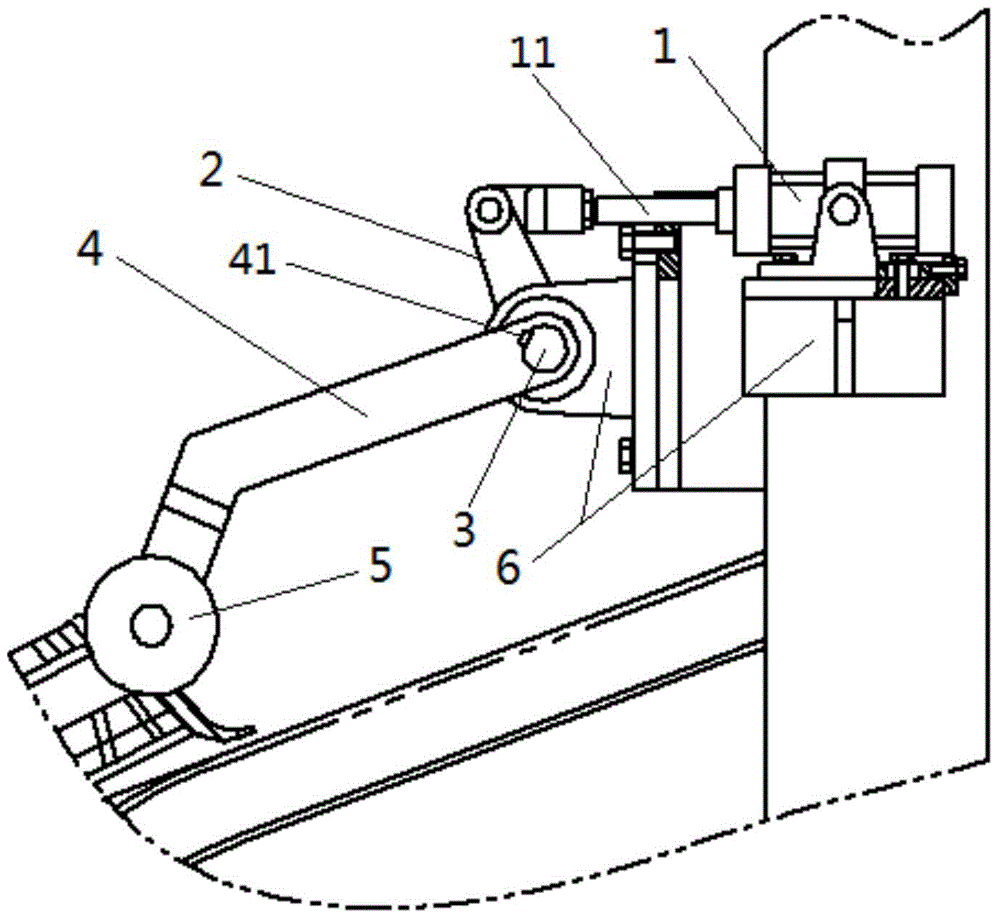
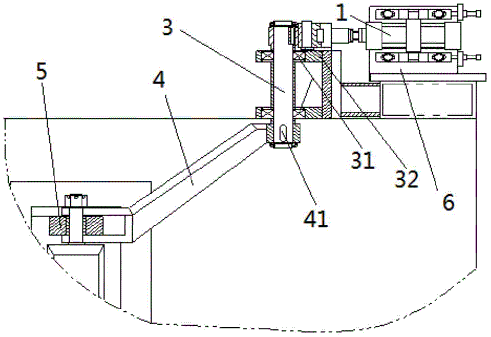
[0016] Such as figure 1 with figure 2 As shown, a secondary knocking device for aluminum ingot demoulding of an aluminum ingot production line includes a cylinder 1, a crank 2, a rotating shaft 3, a connecting rod 4, a hammer 5 and a monitoring device (not shown); the cylinder 1 It is a pneumatic cylinder with a single piston rod, and the cylinder 1 is fixed on the console 6 of the demoulding device of the aluminum ingot production line; the rotating shaft 3 is provided with two bearings 31, and the inner ring of the bearing 31 is fixedly connected with the rotating shaft 3, The outer ring of the bearing 31 is fixedly connected with the bearing mounting frame 32 fixed on the console 6; the free end of the piston rod 11 of the cylinder 1 is correspondingly provided with one end of the crank 2, and a pin or a bolt is arranged in the through hole, so that The free end of the piston rod 11 is rotatably connected to one end of the crank 2, the rotating shaft 3 is fixedly connecte...


PUM


Abstract

The invention discloses a secondary knocking device for the aluminum ingot de-molding of an aluminum ingot production line, and aims to solve the problems of manpower waste, cost increase and low safety of a manual de-molding manner. The device comprises monitoring equipment, a cylinder, a crank, a rotating shaft, a connecting rod and a knocking hammer, wherein the free end of a piston rod of the cylinder is connected with one end of the crank in a rotating manner; the rotating shaft is fixedly connected with the other end of the crank; one end of the connecting rod is fixedly connected with the rotating shaft, and the knocking hammer is arranged at the other end of the connecting rod; after an aluminum ingot which is not smoothly de-molded in a die is monitored by the monitoring equipment, the piston rod of the cylinder extends or retracts to drive the crank to rotate to further drive the knocking hammer through the connecting rod to upwards raise / downwards knock the die to separate the aluminum ingot from the die. When the device is used for knocking the die with the aluminum ingot which is not smoothly de-molded at a de-molding position, a worker is not required to be arranged at the position, so that manpower waste is avoided, production cost is reduced, the de-molding rate of the aluminum ingot is ensured, and the running safety of the device is improved.

Description

technical field [0001] The invention relates to an aluminum ingot demoulding device in an aluminum ingot casting production line, in particular to a knocking device for secondary knocking on a mold when the aluminum ingot is demoulding. Background technique [0002] In the aluminum ingot casting production line, the high-temperature aluminum liquid formed by electrolysis flows into the mold and is initially cooled to form the aluminum ingot. The demoulding device separates the preliminarily formed aluminum ingot from the mold, so that the aluminum liquid can be cast in the mold for the next time. However, the aluminum ingot demoulding device cannot guarantee that the demoulding rate of the aluminum ingot reaches 100%. Occasionally, the aluminum ingot cannot be separated from the mold at the demoulding position, so that the aluminum ingot remains in the mold after passing the demoulding position. It will lead to two situations: 1. The aluminum ingot stays in the mold all the...

Claims


Application Information

Patent Timeline
Patent Type & Authority Applications(China)
IPC IPC(8): B22D7/12
Inventor 郭俊锋雷春丽芮执元冯瑞成赵俊天刘军杨建军辛舟沈浩罗德春
Owner LANZHOU UNIVERSITY OF TECHNOLOGY
Why Eureka
Try Eureka