
Hard alloy combined screw tap

A cemented carbide and composite technology, applied in the direction of metal processing equipment, tangent devices, manufacturing tools, etc., can solve the problems of difficult high-speed cutting, poor heat resistance and wear resistance, easy to break, etc.

Inactive Publication Date: 2015-07-29
丹阳市盛力机械有限公司
View PDF6 Cites 2 Cited by
  • Summary
  • Abstract
  • Description
  • Claims
  • Application Information

AI Technical Summary

Problems solved by technology

[0002] Existing taps are roughly divided into tool steel, high-speed steel, high-speed steel powder metallurgy, solid carbide, etc. according to material classification. Among them, the performance of tool steel taps cannot be compared with the latter three. Therefore, Slightly high-end taps are made of the latter three. Compared with taps made of solid carbide, high-speed steel and high-speed steel powder metallurgy taps have higher toughness than cemented carbide, but their heat resistance And wear resistance is poor, it is not easy to cut at high speed. In addition, because the quenching hardness is not as good as that of cemented carbide, it limits its processing on some harder parts. After quenching, the hardness of the wire tooth section of high-speed steel is also Higher, which will inevitably reduce the toughness and increase the probability of breaking. Therefore, the heat resistance and wear resistance of high-speed steel taps are not as good as those of cemented carbide, while the overall cemented carbide taps have higher wear resistance and heat resistance. It is suitable for high-speed cutting and processing of hard parts, which can significantly improve production efficiency and reduce production costs. However, cemented carbide has poor toughness and is prone to fracture. The characteristics of cemented carbide taps are reduced. Its scope in the processing field

Method used


Image

  • Hard alloy combined screw tap
  • Hard alloy combined screw tap
  • Hard alloy combined screw tap

Examples


Embodiment Construction

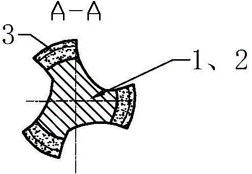
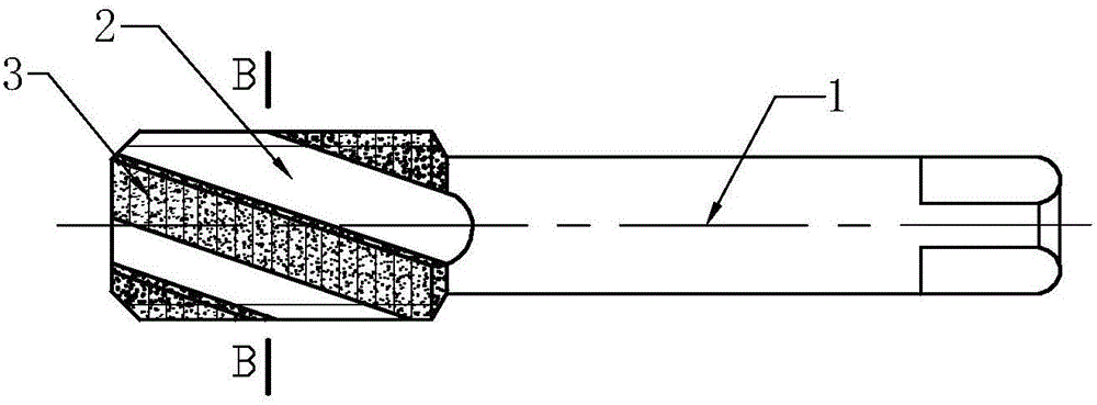
[0018] The cemented carbide composite tap of the present invention will be described in further detail below in conjunction with the accompanying drawings and specific embodiments.

[0019] As shown in the figure, the cemented carbide composite tap of the present invention includes a rod part 1 and a cutting part 2. The cutting part 2 is divided into an inner and outer two-layer structure, and the inner layer structure of the cutting part 2 and the rod part are integrally formed of steel materials. The matrix is ​​formed, that is to say, the lower end of the shank is provided with a cutting part. The shank of the tap and the inner structure of the cutting part 2 (the matrix of the tap) are preferably the same material with high toughness, and the outer structure of the cutting part 2 is a belt. The outer ring 3 with a cutting edge, the outer structure of the cutting part 2 is made of cemented carbide material, that is to say the outer ring is made of cemented carbide material, ...


PUM


Abstract

The invention discloses a tool for machining inner hole threads, and particularly relates to a hard alloy combined screw tap which comprises a rod and a cutting portion. The cutting portion is divided into an inner layer and an outer layer, the inner layer of the cutting portion and the rod are integrally formed by the aid of steel materials, and the inner layer of the cutting portion is integrally welded with the outer layer of the cutting portion. By the aid of the structure, as the cutting portion is divided into the inner layer and the outer layer, the inner layer is made of materials with high toughness, the outer layer is made of hard alloy materials, abrasion resistance and heat resistance of a hard alloy screw tap are achieved, the toughness of a high-speed steel wire tap is exceeded, the hard alloy combined screw tap does not easily fracture and is suitable for high-speed cutting, production efficiency is improved, a large number of hard alloy materials are saved as compared with an integrated hard alloy screw tap, a lot of high-speed steel is saved as compared with the high-speed steel wire tap, and production cost is reduced.

Description

technical field [0001] The invention relates to a cutting tool for machining inner hole threads, in particular to a cemented carbide composite tap. Background technique [0002] Existing taps are roughly divided into tool steel, high-speed steel, high-speed steel powder metallurgy, solid carbide, etc. according to material classification. Among them, the performance of tool steel taps cannot be compared with the latter three. Therefore, Slightly high-end taps are made of the latter three. Compared with taps made of solid carbide, high-speed steel and high-speed steel powder metallurgy taps have higher toughness than cemented carbide, but their heat resistance And wear resistance is poor, it is not easy to cut at high speed. In addition, because the quenching hardness is not as good as that of cemented carbide, it limits its processing on some harder parts. After quenching, the hardness of the wire tooth section of high-speed steel is also Higher, which will inevitably r...

Claims


Application Information

Patent Timeline
IPC IPC(8): B23G5/06
CPCB23G5/06
Inventor 王仲林
Owner 丹阳市盛力机械有限公司
Learn More