Polishing grinding machine for LED ceramic bracket

A technology for ceramic brackets and grinding machines, which is applied to the parts of grinding machine tools, grinding/polishing equipment, grinding/polishing safety devices, etc. It can solve the problems of inconsistent polishing surface effects, low processing efficiency, and affecting processing efficiency. To achieve the effect of ensuring the quality of polishing and grinding, improving the processing efficiency and improving the processing effect

Inactive Publication Date: 2015-07-29
DONGGUAN KECHENDA ELECTRONICS TECH
View PDF7 Cites 5 Cited by
  • Summary
  • Abstract
  • Description
  • Claims
  • Application Information

AI Technical Summary

Problems solved by technology

[0002] The LED ceramic bracket is a plate-shaped workpiece. After processing and forming, its surface usually requires a polishing machine to polish. In the prior art, some of them are manually polished, and the processing efficiency is extremely low. At the same time, it is often caused by artificial Errors make it difficult to obtain a consistent surface finish;
[0003] Later, some automatic polishing machines appeared, for example, a belt polishing machine disclosed in the invention patent document with application number 201410361029.2, which is mainly suitable for flat workpieces, and the workpieces are transported along the conveyor belt, and are subjected to There are many defects in the polishing process of the abrasive belt, for example: during the conveying process of the workpiece on the conveyor belt, it is easy to shift, so that the required polishing surface cannot be polished at one time, which affects the processing efficiency and easily leads to inconsistencies in the effect of the polished surface Bad phenomenon; there are also workpieces (such as LED ceramic brackets) in the process of conveying and polishing, which are very easy to reduce the product quality of the workpiece due to frictional overheating, such as deformation, etc.

Method used


Image

  • Polishing grinding machine for LED ceramic bracket
  • Polishing grinding machine for LED ceramic bracket
  • Polishing grinding machine for LED ceramic bracket

Examples


Embodiment Construction

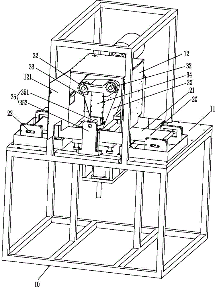
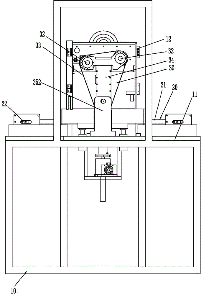
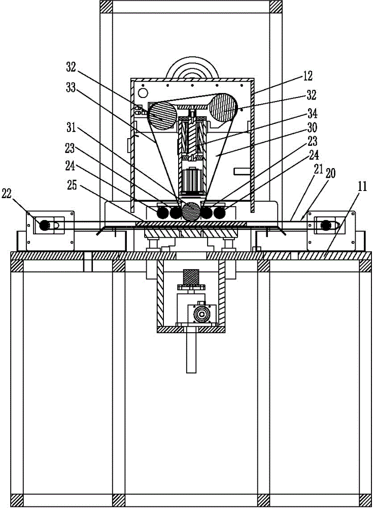
[0045] Please refer to Figure 1 to Figure 8 As shown, it has shown the concrete structure of the embodiment of the present invention, and it comprises frame 10, workpiece conveying device 20, polishing and grinding device 30 and PLC controller 41, wherein, is formed with polishing and grinding work on this frame 10 The platform 11, the workpiece conveying device 20 and the polishing and grinding device 30 are arranged on the polishing and grinding working platform 11, and the PLC controller 41 is connected and controlled to the workpiece conveying device 20 and the polishing and grinding device 30 respectively.

[0046] The workpiece conveying device 20 includes a conveyor belt 21, a conveyor roller shaft 22 for driving the conveyor belt 21 to move horizontally, and a motor for driving the conveyor roller shaft 22. The aforementioned PLC controller 41 is connected and controlled to the motor. Here, the The motor is defined as the first motor 42; the conveyor belt 21 is provid...


PUM


Abstract

The invention discloses a polishing grinding machine for an LED ceramic bracket. The polishing grinding machine comprises a rack, a workpiece conveying device, a polishing grinding device and a PLC controller. The workpiece conveying device comprises a conveying belt, a conveying roll shaft and a motor. A locating roll shaft is arranged above the conveying belt. The polishing grinding device comprises a vertical pedestal, a drive wheel, a driven wheel, and an abrasive belt. The conveying belt is provided with a pressure sensor. The driven wheel is provided with a lifting drive structure. Moreover, the abrasive belt is provided with an offset sensing switch for sensing a positional deviation of the abrasive belt and a correcting mechanism for pushing and correcting an abrasive belt winding position. The PLC controller is respectively connected with the motor, the pressure sensor, the lifting drive mechanism, the offset sensing switch and the correcting mechanism. The automation degree and the intelligent degree of the polishing grinding machine are increased greatly by automatically sensing a contact pressure between the abrasive belt and a workpiece, automatically sensing the winding position of the abrasive belt, and automatically regulating the contact pressure and the winding position in real time based on the actual conditions, accordingly increasing the machining efficiency and guaranteeing the polishing grinding quality better.

Description

technical field [0001] The invention relates to a polishing grinder, in particular to a polishing grinder for an LED ceramic bracket. Background technique [0002] The LED ceramic bracket is a plate-shaped workpiece. After processing and forming, its surface usually requires a polishing machine to polish. In the prior art, some of them are manually polished, and the processing efficiency is extremely low. At the same time, it is often caused by artificial Errors make it difficult to obtain a consistent surface finish; [0003] Later, some automatic polishing machines appeared, for example, a belt polishing machine disclosed in the invention patent document with application number 201410361029.2, which is mainly suitable for flat workpieces, and the workpieces are transported along the conveyor belt, and are subjected to There are many defects in the polishing process of the abrasive belt, for example: during the conveying process of the workpiece on the conveyor belt, it is...

Claims


Application Information

Patent Timeline
Patent Type & Authority Applications(China)
IPC IPC(8): B24B21/04B24B21/18
CPCB24B21/04B24B21/18B24B51/00B24B55/02B24B55/08
Inventor 骆阳旭吴朝晖
Owner DONGGUAN KECHENDA ELECTRONICS TECH
Why Eureka
Try Eureka