Novel high-speed motor train unit non-power bogie

A technology for high-speed EMUs and power bogies, which is applied in the directions of bogies, devices for lateral relative movement between the underframe and the bogies, and railway car body components, which can solve the problem of unfavorable lightweight design of bogies. , The overall structure of the bogie is complex, and the stress concentration at the joint is large, so as to improve the welding process, optimize the dynamic performance, and reduce the stress concentration.

Inactive Publication Date: 2015-07-29
CRRC CHANGCHUN RAILWAY VEHICLES CO LTD
View PDF8 Cites 10 Cited by
  • Summary
  • Abstract
  • Description
  • Claims
  • Application Information

AI Technical Summary

Problems solved by technology

The overall structure of the above-mentioned bogie is complex, the weight is relatively large, and the space occupied by the external installation and bearing parts is large, which is not conducive to the lightweight design of the bogie itself and the improvement of vehicle speed
Among them, the H-shaped welded frame is usually composed of two side beams and a cross beam. The beam is composed of round steel pipes. Due to the structural shape of the connection between the round steel pipe and th

Method used


Image

  • Novel high-speed motor train unit non-power bogie
  • Novel high-speed motor train unit non-power bogie
  • Novel high-speed motor train unit non-power bogie

Examples


Embodiment Construction

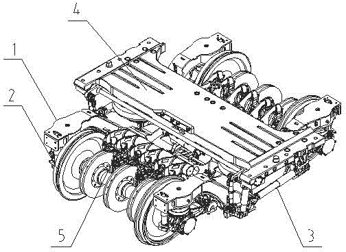
[0015] Such as figure 1 As shown, the non-power bogie of the high-speed EMU mainly includes a frame 1, a wheel-to-axle box positioning device 2, a secondary suspension device 3, a corbel device 4, and a foundation brake device 5.

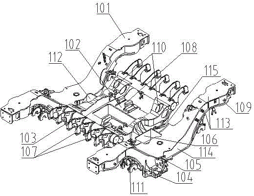
[0016] Such as figure 2 As shown, the frame includes a pair of side beams 101 connected to each other through a pair of cross beams 102. The cross beams and side beams form a hollow box structure. Longitudinal beams 106 are also box structures between the beams. The cross beams 102 adopt four It is welded from one piece of steel plate, and the cross beam side vertical plate 112 is directly inserted into the side beam upper and lower cover plate 113 and connected with the side beam side vertical plate 114; The plates are connected with variable cross-sections through the transition piece 115 . A pair of small longitudinal beams 110 are welded on the longitudinal beam 106, and a pair of brake beam round steel pipes 103 are welded at the ends of the...


PUM


Abstract

The invention relates to a novel high-speed motor train unit non-power bogie. The novel high-speed motor train unit non-power bogie comprises a framework, a wheel pair, a primary fastening suspension device, a secondary fastening suspension device, a traction device and a foundation brake device, wherein a crossbeam and side beams of the framework respectively adopt a box-type structure formed by welding steel plates, a main body consists of two side beams and a crossbeam, the crossbeam and each side beam are respectively formed by welding steel plates, the crossbeam and each side beam are respectively provided with various functional seat in a welding manner, the crossbeam and each side beam are connected with each other in a plugging manner, an upper cover plate and a lower cover plate of each side beam extend inwards, a side vertical plate of the crossbeam is directly inserted in the extension position of the upper cover plate and the lower cover plate of the side beam and directly connected with the inner vertical plate of the side beam, the lower cover plates of the crossbeam and each side beam are directly connected with each other in a welding manner, and the upper cover plates of the crossbeam and the side beams are connected in a variable cross section manner by virtue of a transitional connecting block; a small longitudinal beam is welded on the crossbeam, and brake beam is connected with the upper cover plate of the crossbeam and the small longitudinal beam in welding manner. The bogie is simple in structure, so that the application, maintenance and repairing can be facilitated; the modularized and uniform design of parts can be realized, so that the applicability of products can be improved, and the fatigue service life of the bogie can be prolonged.

Description

technical field [0001] The invention relates to a non-power bogie for a rail vehicle, in particular to a new non-power bogie for high-speed standard EMUs with high parts interchangeability, convenient operation and maintenance, and meeting performance requirements. Background technique [0002] With the development of high-speed railways, the types of vehicles are increasing day by day, the operation and maintenance management is difficult, and the maintenance cost is high. High requirements, at the same time have a greater impact on vehicle dynamics. Therefore be badly in need of inventing a kind of non-powered bogie of new high-speed standard EMU with high interchangeability of parts, easy operation and maintenance to meet the performance requirements of the application. [0003] The existing high-speed EMU non-power bogie usually includes a welded H-shaped frame, and two wheel-to-axlebox devices are arranged under the frame. The frame and the wheel-set are connected by a...

Claims


Application Information

Patent Timeline
IPC IPC(8): B61F5/52B61F5/30B61F5/24
CPCB61F5/52B61F5/24B61F5/30
Inventor 范军周殿买李国栋
Owner CRRC CHANGCHUN RAILWAY VEHICLES CO LTD
Why Eureka
Try Eureka